Installation
Instructions for the VRD-1FFj. |
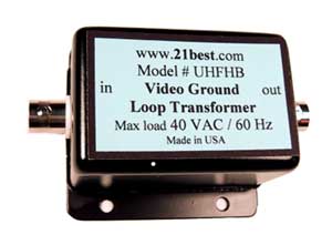
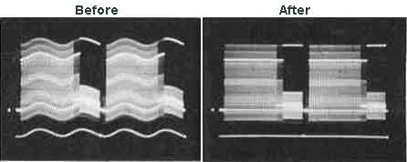
Solves "Ground
Loop" and "Hum Bar" problems.
For analog and
digital cable TV and cable modems.
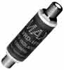
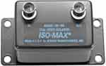
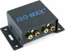
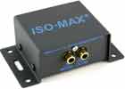
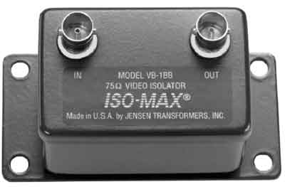
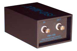
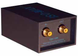
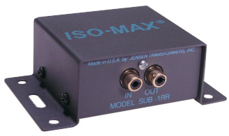
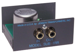
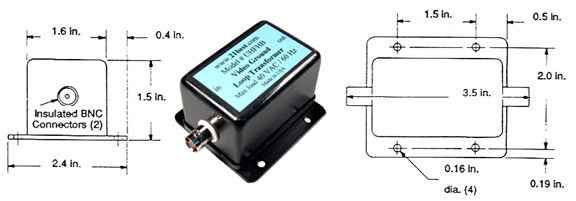
Two female "F" connectors, one "F" in and one "F" out. VRD-1FFj , 2 MHz to 1300
MHz bandwidth.
|
| |
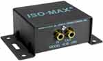
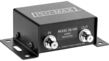
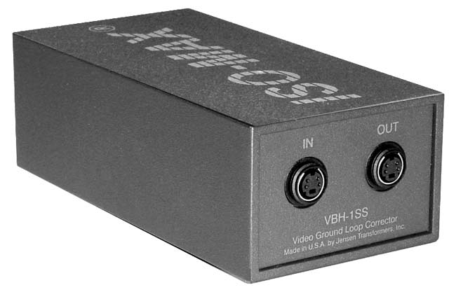
USER GUIDE CATV ISOLATOR MODEL VRD-1FF |
This series of video ground isolation interfaces are designed for use in the finest professional and home theater
systems. They have been engineered with the same standards of excellence as the Jensen series of audio transformers, which have
been installed in tens of thousands of recording studios, broadcast facilities, and sound reinforcement venues worldwide. Jensen
audio transformers have become the industry benchmarks for sonic transparency because of their extremely wide bandwidth,
low harmonic distortion, and extremely low phase distortion. The Jensen series of video ground isolation interfaces meet the
same level of unparalleled performance.
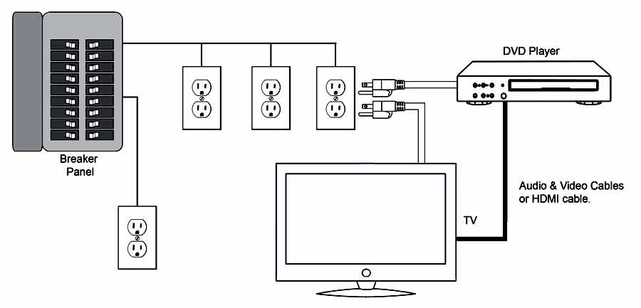
Model VRD-1FF is a one channel CATV ground isolator designed to solve a ground loop problem that can show up as a hum
or buzz problem in either the audio or video portion of a professional A/V or home theater system. These ground loops occur
because the coax cable from the cable TV provider is grounded outside the building or residence (required by National Electric
Code), and this ground becomes an alien ground to the AC power safety ground inside, creating the ground “loop”.
The model VRD-1FF is a capacitive based isolator which provides a high impedance barrier to AC power related ground currents,
preventing this hum or buzz in sound systems or “hum bars” in video systems. The VRD-1FF was designed specifically to be
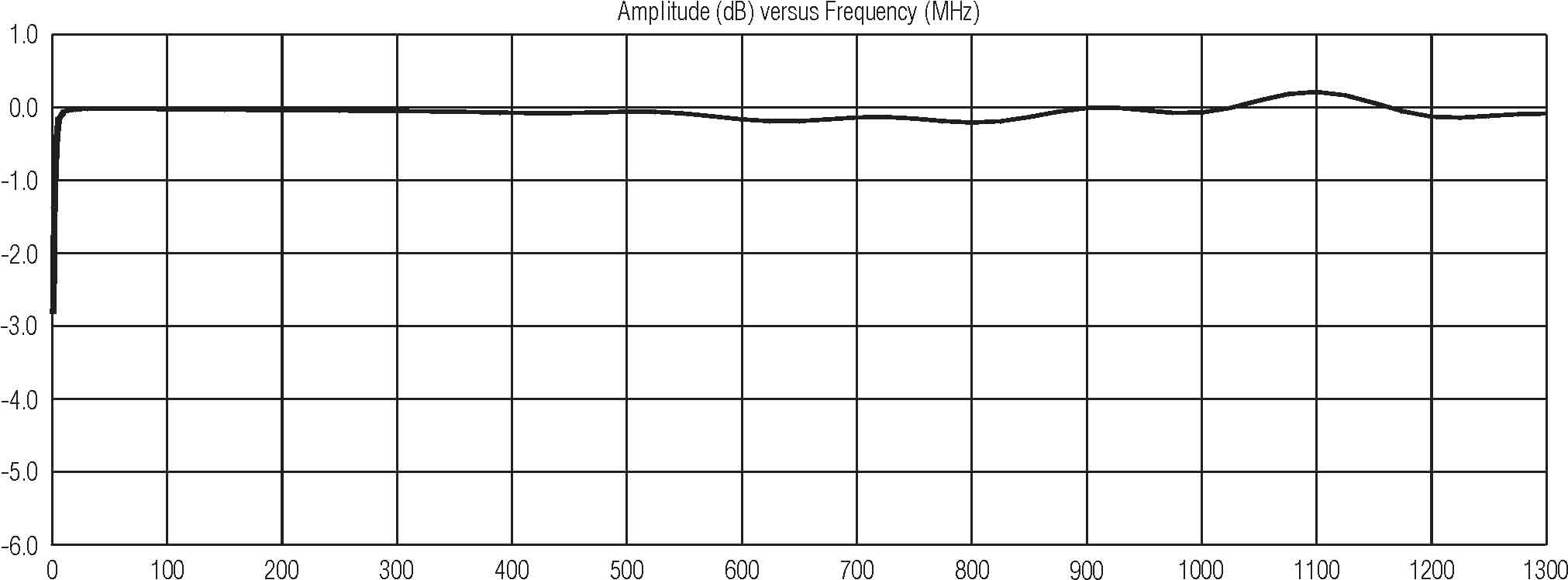
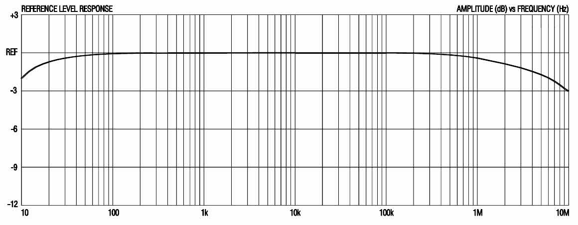
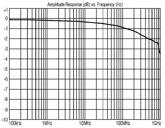
a completely transparent path for video and cable modem signals. Unlike other low-cost CATV isolators available, the VRD-1FF
has ruler-flat response and wide enough bandwidth to not cause an interruption of cable modems, the two-way communication
between the cable provider and their set-top box, and any of the upper range channels. In other words, the VRD-1FF works where
others don’t!
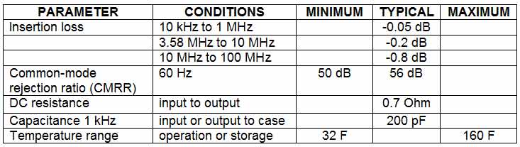
Model VRD-1FF Specifications
Bandwidth . . . . . . . . . . . . . . . . . . . . . . . . . . . . . . . . . . . . . . . . . . . . . . . . . . . . . . . . . . . . . . . . . . . . . . . 2 MHz to 1300 MHZ
Insertion Loss (typical) . . . . . . . . . . . . . . . . . . . . . . . . . . . . . . . . . . . . . . . . . . . . . . . . . . . . . . . . . . . . . . .. . . . . . . . . -0.19 dB
Capacitance (output shield to input shield, 1 kHz) . . . . . . . . . . . . . . . . . . . . . . . . . . . . . . . . . . . . . . . . . . . . . . . . . . . 2000 pF
PROPER INSTALLATION IS ESSENTIAL TO ACHIEVE OPTIMUM PERFORMANCE
PLEASE READ THIS GUIDE CAREFULLY !
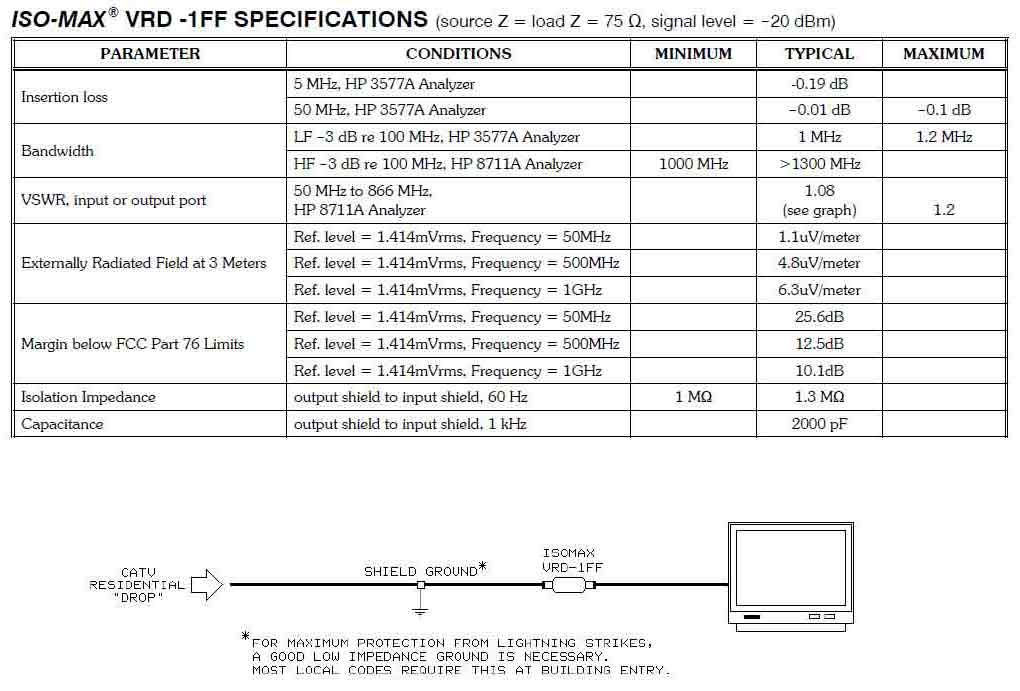
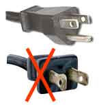
NOTE: The VRD-1FF isolator must be installed inside your home, after the point where the
cable company has grounded your cable outside. This is a safety ground required by electric
code to prevent a lightning strike from entering your home, and must not be defeated.
If you do not see evidence that your cable is grounded outside (possibly because of an
underground feed), or if you know that someone has removed the ground, CALL YOUR
CABLE COMPANY NOW, and get them to add the necessary ground connection ASAP.
We recommend that the VRD-1FF isolator be installed on the coax cable run in the room where you are
experiencing a hum problem. If you install the VRD-1FF at the point where the cable enters your residence,
but before a multi-tap cable splitter, you will be isolating the cable ground outside from the input to the
splitter only. All of the splitter’s outputs will still be grounded together, raising the possibility that you
might still have a ground loop between two or more of the splitter’s output destinations. The optimum place
to install the VRD-1FF is directly at the back of the cable company’s set-top box (if you have one) or at the
point it enters your system (TV input, VCR input, Control Amp input, etc.).
NOTE: The next page contains important information about the proper installation of the
VRD-1FF. We strongly recommend that you read our instructions and follow them.
Failure to do so can lead to damage to the connectors on the VRD-1FF. This type of
damage is not covered under the warranty policy.
Installation Instructions for the VRD-1FF
Step 1. Remove your existing coax cable at the system’s entry point. STOP ! READ STEP 2 NOW !
Step 2. Before going any further, you must inspect the condition of your existing coax cable’s center
conductor (the solid wire in the center of the F-connector). The end of the center conductor must be
smooth, straight, cleanly cut, and should not extend past the edge of the nut; trim if needed. If it is bent
over in any way, gently straighten it with a pair of thin-nosed pliers before proceeding. If the end has
any significant flare to it because it was cut by a pair of dull wire cutters, it must be cleaned up before
you install the VRD-1FF. This flare will damage the gold-plated contacts inside the VRD-1FF
female F-connectors, causing a bad connection which can result in lost channels and poor
performance. This type of damage to the VRD-1FF’s connectors will not be covered by warranty.
Step 3. Once you have determined that the end of the center conductor on your existing coax cable is
clean and of the proper length, you can install the VRD-1FF. Hold the VRD-1FF isolator in one hand,
and insert your coax cable into either end of the isolator (the VRD-1FF is bi-directional). Now, turn the
nut on your existing coax cable’s connector until snug. Do not rotate the VRD-1FF; you want to spin the
nut only. Rotating the VRD-1FF is what causes the aforementioned damage to the VRD-1FF’s
connectors by the flared-out end of the existing coax cable’s center conductor.
Step 4. Now, attach an additional coax cable (not provided) to the other end of the VRD-1FF. Use a
short (6" to 1' or so) cable if you can find one. As before, hold the VRD-1FF still, and rotate the nut on
the short cable’s connector until snug.
Step 5. Finally, insert the other end of the short cable into your system’s input, and tighten the nut snug.
Step 6. Turn on your system, and enjoy the hum-free signals you are now experiencing!
Troubleshooting Section
Question 1: My hum is gone, but now I’am no longer able to get certain channels. What’s wrong?
This can occur occasionally. We have been investigating this problem for a while now, and have
discovered it is due to one of two reasons:
a. In most of these cases, the connectors of the VRD-1FF have been damaged enough from a bad
coax end to cause a poor connection. The fix is to make sure your coax cable’s end is clean before you
install the VRD-1FF.
b. The other reason this occurs is due to reflections of the video signal occurring at points along
the feed between the cable company and your home. Video reflections can be caused by improper tuning
of the cable company’s repeater amplifiers, illegal wire taps into the cable system (such as in apartment
buildings), or unused video outlets in your home. Unused outlets must have a 75 Ohm terminator
attached to the F-connector to prevent reflections. Go to an electronics store (i.e.: Radio Shack), purchase
these terminator(s), and install them on all unused video outlets first as a possible fix.
If you still have missing channels, try moving the VRD-1FF to the other end of the coax cable
run in the room it is in. We have found that changing the lengths of the cables that are before and after
the VRD-1FF is enough to eliminate the reflections that are causing the dropped channels.
If You Need Help
If you experience difficulty or have technical questions, our staff engineers are available from 9 AM to 5
PM Pacific time, Monday through Thursday, by calling (818) 374-5857or our toll-free (866) 476-6291.
You may also reach us by FAX 24 hours a day, 7 days a week at (818) 374-5856 or e-mail us at
info@jensen-transformers.com.
Several Jensen application notes discuss the technical aspects of grounding and interfacing in audio and
video systems. They are available free on request. This information, as well as data on our full line of
products for audio and video, may be obtained from our web site at www.jensen-transformers.com.
PRODUCT WARRANTY
For a period of 1 YEAR after purchase, Jensen Transformers, Inc. will, free of charge, repair or replace
any part of this product that fails due to defective materials or workmanship. This limited warranty is
subject to the following limitations:
1. Defects that are, in the sole judgment of Jensen, the result of accident, misuse, abuse, neglect,
mishandling, misapplication, faulty installation, unauthorized repair, modification, or acts of
God will not be covered by this warranty.
2. In the absence of proof of date of purchase, the date of manufacture (as determined from lot
numbers of internal parts and the records of Jensen Transformers, Inc.) shall be used in its place.
3. There are no express warranties except as listed above.
4. JENSEN TRANSFORMERS, INC. SHALL NOT BE LIABLE FOR INCIDENTAL OR
CONSEQUENTIAL DAMAGES RESULTING FROM THE USE OF THIS PRODUCT OR
ARISING OUT OF THE BREACH OF THIS WARRANTY. Duration of implied warranties, if
any, is limited to 12 months.
If a problem develops with this product during the warranty period, call or write us before attempting
any repair. We can help you identify specific problems, and possibly solve the problem, before the unit
is returned to us for repair or replacement. In any case, DO NOT RETURN THE UNIT WITHOUT
AUTHORIZATION and instructions from us. Jensen cannot be responsible for damage due to shipping
or improper packaging.
JENSEN TRANSFORMERS, INC.
|
Data Sheet
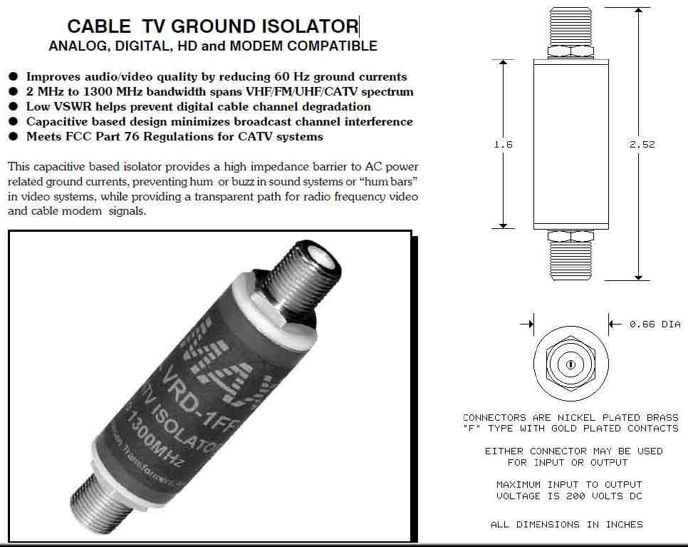
CABLE TV GROUND ISOLATOR
ANALOG, DIGITAL, HD and MODEM COMPATIBLE |
Improves audio/video quality by reducing 60 Hz ground currents
2 MHz to 1300 MHz bandwidth spans VHF/FM/UHF/CATV spectrum
Low VSWR helps prevent digital cable channel degradation
Capacitive based design minimizes broadcast channel interference
Meets FCC Part 76 Regulations for CATV systems
This capacitive based isolator provides a high impedance barrier to AC power
related ground currents, preventing hum or buzz in sound systems or .hum bars.
in video systems, while providing a transparent path for radio frequency video
and cable modem signals. |
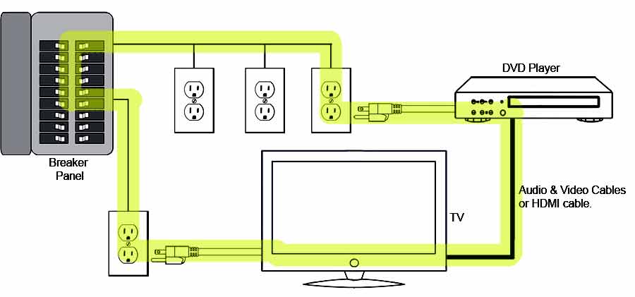
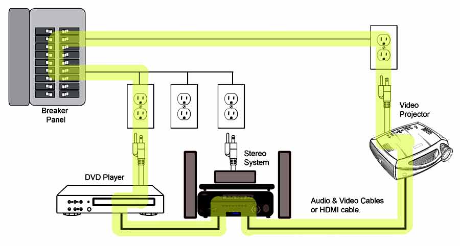
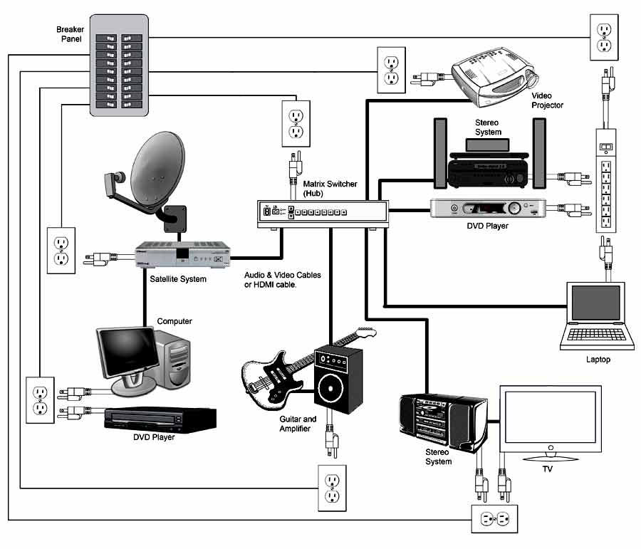
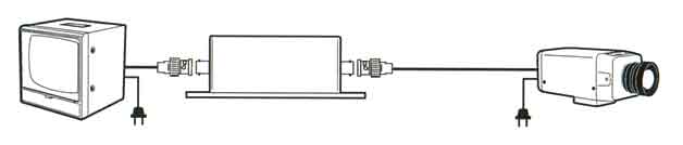
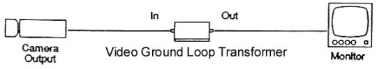
Typical Application Hookup |
All minimum and maximum specifications are guaranteed.
Unless noted otherwise, all specifications apply at 25EC. Specifications subject to change without notice.
All information herein is believed to be accurate and reliable,
however no responsibility is assumed for its use nor for any infringements of patents which may result from its use.
No license is granted by implication or otherwise under any patent or patent rights of Jensen Transformers, Inc.
IMPORTANT NOTE: THIS PRODUCT IS NOT INTENDED FOR USE IN CIRCUMSTANCES
WHERE THE DC OR PEAK AC VOLTAGE BETWEEN INPUT AND OUTPUT CONNECTIONS EXCEEDS
34 VOLTS OR WHERE ITS FAILURE COULD CAUSE INJURY OR DEATH.
|
|