|
|
|
||||||||||||||||||||||||||||||||
 |
|
||||
  |
 |
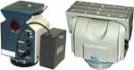
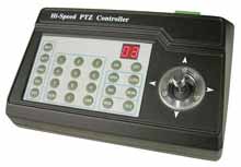
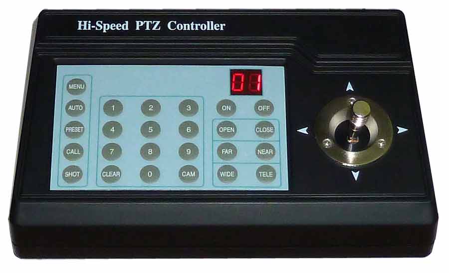
| Joystick Controller for Pan and Tilt. Controls all the functions of 1 to 32 motors, including pan and tilt direction. Maximum cable length from the controller to the pan tilt motor is 1200 feet. |
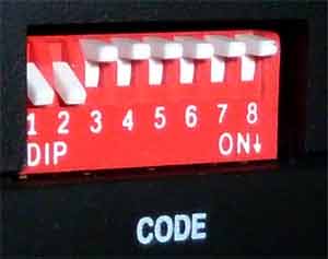
The correct standard positions of the switches on the rear of the joystick controller. This is how the new systems are shipped. |
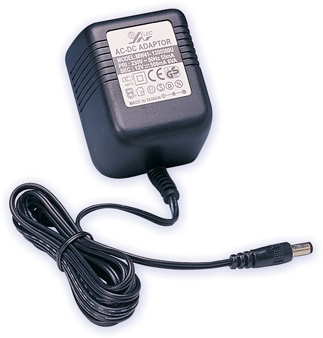
Joystick Controller for Pan and Tilt. Controls all the functions on 1 to 32 motors, including pan and tilt direction. Maximum cable length from the controller to the pan tilt motor is 1200 feet. Compact Design, attractive. Input Power : 12 VDC Power consumption : 5 Watts Weight is 1 pound. Temperature range: +35 F to +100 F Power supplies 12 VDC 500 mA |
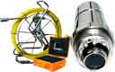
| Allows you to move the camera up & down, right & left over a wired hand held remote control. |
|
|||
|
|||
|
|||
 |
|||
 |
|||
 |
|||
|
The correct standard positions of the switches on the rear of the joystick controller. This is how the new systems are shipped. | ||
 |
|||
 |
|||
 |
|||
 |
|||
 |
|||
SAFETY PRECAUTIONS |
CAUTION: Risk of Electric
shock. Do not open. CAUTION:To reduce the risk of electrical shock. Do not open covers. No user serviceable parts inside. Refer servicing to qualified service personnel. GRAPHIC SYMBOLS EXPLANATION: The lighting flash with a arrowhead symbol, in an equilateral triangle, is intended to alert the user. There is uninsulated "dangerous voltage" presence near the product's enclosure which may be a risk to people. The exclamation point within an equilateral triangle is to alert the user to reference of the important operating and maintenance (servicing) instructions. Page A. |
INDEX; a. Summary; Introduction of Function ...................................Page 1 b. Introduction of the Keyboard's Panel ................................Page 2 c. Setting of the Keyboard .....................................................Page 3 d. Operation of the Keyboard ................................................Page 5 e. Installation and Connection; Technical Specifications ...........Page 8 f. Points for Attention..............................................................Page 9 |
1. Summary: |
3. Introduction of the keyboard Panel: |
b. Rear Panel (Figure 2) A. Power input connector: input DC 12 V power. B. DC 12 V Output. C. Communication connector RS485. D. ID-Code switch: Used to set the protocol in use and the baud rate of communications. 4. Setting of the Keyboard a) The protocol in use and the baud rate of communication of the keyboard are set by the ID-Code in Figure 2. DIP 1-DIP 4 are used to select type of the communication protocol as per following table. b) DIP 5 and DIP 6 are used to select the baud rate, shown as following table (DIP 7 and DIP 8 are not used): c) Some of the ID-Code of the protocols are set as follows: Page 4 |
5. Operation of the Keyboard |
Auto Pan Position (First specify position, second specify
position) |
.For different camera, control function
in the list could be different. .For the camera with the menu, switch ON/OFF the menu by (MENU)+(3)+(0n), and switch ON/OFF the .OSD by (MENU)+(3)+(OFF). In case the camera has the menu and the menu of ON. ..1. Select the item on the menu by buttons (WIDE)/(TELE) to scroll the cursor up or down. ..2. Change the status of the selected item on the menu by buttons (FAR)/(NEAR). ..3. Switch OFF the menu as per operations in the list after the menu is set. .Take care of differences between the Menu of Speed Dome and the Menu of Camera. For the speed dome with the menu, enter the menu by (64)+(CALL) and basic operations are as follows: ..1. Call No. 64 preset point to open the main menu by the control keyboard. ..2. When the menu appears on the screen, move the cursor to the item you need to set by TILT UP and ......TILT ....DOWN, and enter the settings of the item to make change by PAN LEFT and PAN RIGHT. ..3. Speed up operation of the joystick after keeping it for one second in one direction. ..4. All settings of the menu could not be lost even power failure occurred. ..5. Operations under special case can be referred on the description of the menu of the ball machine. 12. Use the Joystick to Control the Speed Dome Camera: .......You can use the speed joystick to control the Pan/Tilt direction and speed of the dome of the camera randomly. The speed of pan/tilt is decided by the angle of the joystick you operated (Figure 3). Change the tilting angle of the joystick you can adjust the speed evenly and the camera can be focused automatically in the course of scan to keep images being distinct. Page 7 |
6. Installation and Connection Attention: Please read the operation manual of the keyboard and the speed dome carefully before connecting wires. Any incorrect connections can cause permanent damage of the device> When connecting wires, first switch off the power supply of all devices. The communication wires between devices should be shielded twisted cable. When installing cables they should be far away from high voltage lines or other possible interference circuits as can as possible. ..1. Connections of the keyboard controller controlling multiple speed dome cameras (figure 4). ..2. Connections between the keyboard and the speed dome camera (Figures 5). 7. Technical Specifications: Communication between Speed Dome Camera and Controller: Port to Multi-port and half duplex function. Communication connector: RS-485. Baud Rate of Communication: Four baud rates i.e. 2400 BPS, 4800 Bps, 9600 Bps and 19200 Bps. Page 8 |
Distance of Communication: 1200 M in maximum. |
Please read the operation manual of
the keyboard carefully before using it. The operation manual is mainly focused on all functions of B01 Protocol. For other different protocols, operations could be something difference and those different parts will be listed on "Supplementary .Description of the Keyboard Controller" in details. The keyboard takes 12 V DC power supply. Please confirm the voltage and polarity before the power supply is switched on. Do not place the keyboard under the rain or on wet place so as to avoid short circuit or electrical shock. As the keyboard is a sophisticated electronic device, you should never open the case so as to avoid the occurrence of trouble. The keyboard has integrated multiple protocols, and you are pleased to select correct protocol and the baud rate. Page 9 |
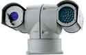
Pan Tilt Zoom (PTZ) CCTV cameras are affordable and offer better performance then ever. Pan Tilt Zoom surveillance cameras are used by Government, large corporations, casinos and consumers. Other uses include Mast Aerial Photography. PTZ cameras rotate horizontally through 360 degrees, vertically through 90 degrees and have motorized optical zoom lenses. A camera turret or motorized swivel is similar to a pan-tilt head. Pan Tilt movement can be very fast and is controlled through a wired (or wireless) connection, by the mating controller. PTZ cameras are often mounted in domes, outside dome cameras are weatherproofed, heated and cooled. |
 |
 |
 |
 |