|
|
|
||||||||||||||||||||||||||||||||
 |
|
||||
|
|
|||||||||||
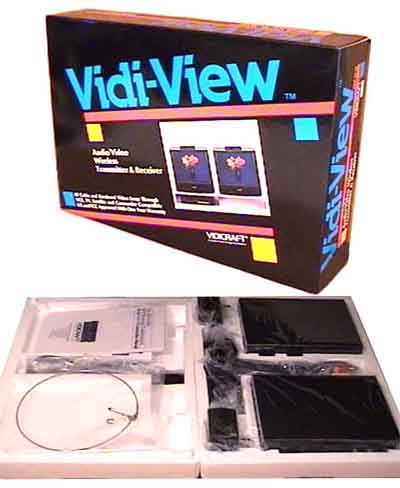 |
Vidi-View The box it comes in. SIZE 7" x 10" x 2" The box contains transmitter,receiver &accessories. |
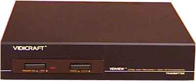 |
Vidi-View Transmitter front |
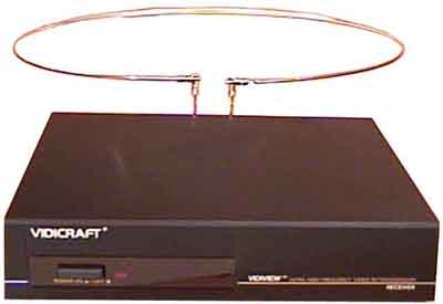 |
Vidi-View Receiver front |
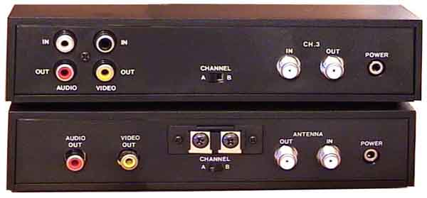 |
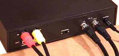
Vidi-View Transmitter rear Receiver rear |
 |
Vidi-View Transmitter connections |
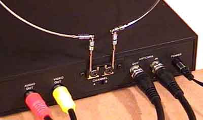 |
Vidi-View Receiver connections |
 |
Get one now |
7 pages from the manual reprinted
below. |
|
 |
 |
 |
 |
An all text version of the manual is reprinted below.
The Vidi-View
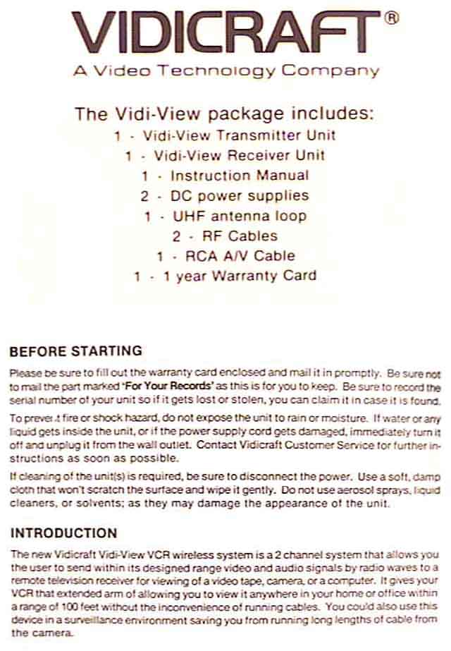
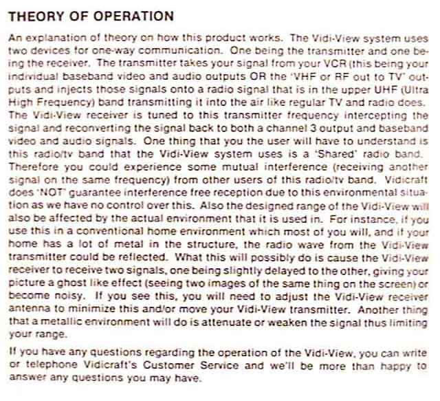
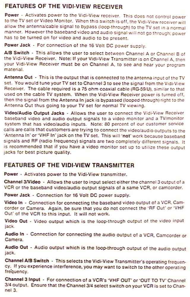
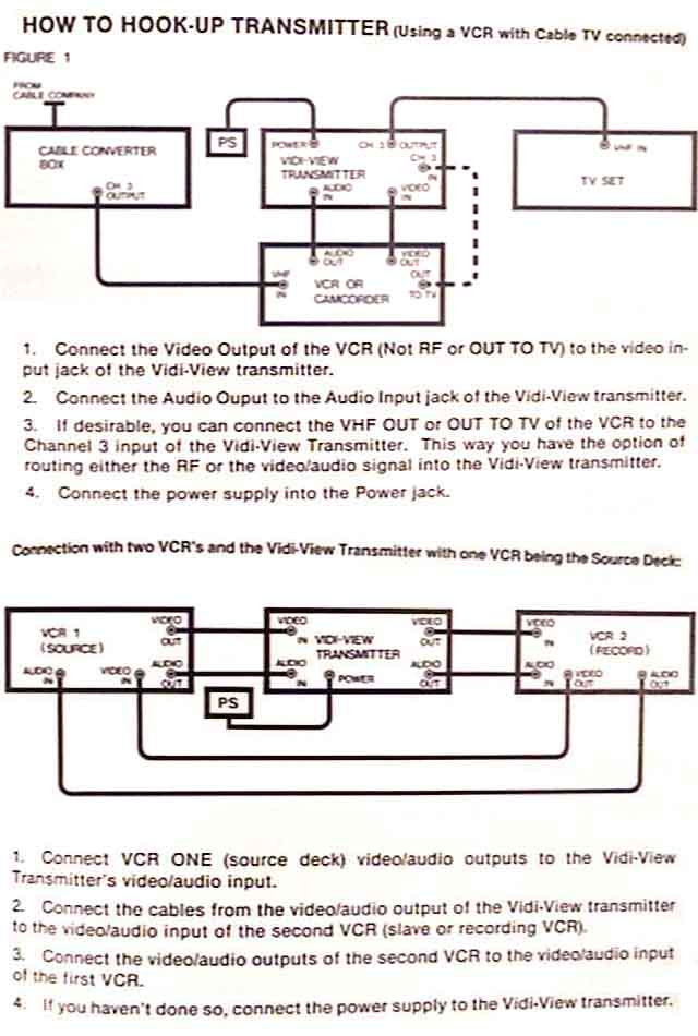
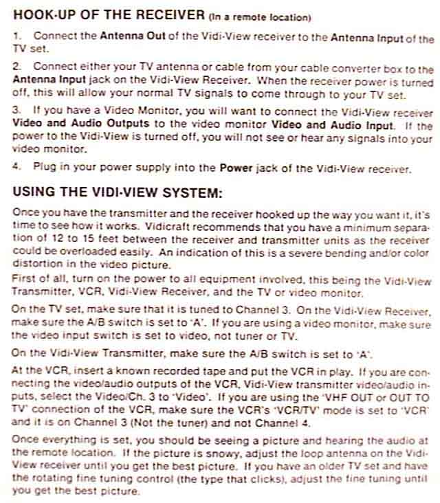
package includes: Vidi-View Transmitter Unit Vidi-View Receiver Unit Instruction Manual DC power supplies UHF antenna loop RF Cables RCA A/V Cable 1 year warranty Card INTRODUCTION The new Vidicraft Vidi-View VCR wireless system is a 2-channel system that allows you the user to send, within its designed range, video and audio signals by radio waves to a remote television receiver for viewing of a video tape, camera, or a computer. It gives your VCR that extended arm of allowing you to view it anywhere in your home or office within a range of 100 feet without the inconvenience of running cables. You could also use this device in a surveillance environment saving you from running long lengths of cable from the camera. THEORY OF OPERATION An explanation of theory on how this product works. The Vidi-View system uses two devices for one-way communication. One being the transmitter and one being the receiver. The transmitter takes your signal from your VCR (this being your individual base band video and audio outputs OR the 'VHF or RF out to TV' outputs and injects those signals onto a radio signal that is in the upper UHF (Ultra High Frequency) band transmitting it into the air like regular TV and radio does. The Vidi-View receiver is tuned to this transmitter frequency intercepting the signal and reconverting the signal back to both a channel 3 output and base band video and audio signals. One thing that you the user will have to understand about this radio/TV band is that the Vidi-View system uses is a 'Shared' radio band. Therefore you could experience some mutual interference (receiving another signal on the same frequency) from other users of this radio/TV band. Vidicraft does 'NOT' guarantee interference free reception due to this environmental situation, as we have no control over this. Also the actual environment that it is used in will also affect the designed range of the Vidi-View. For instance, if you use this in a conventional home environment which most of you will, and your home has a lot of metal in the structure, the radio wave from the Vidi-View transmitter could be reflected. What this will possibly do is cause the Vidi-View receiver to receive two signals, one being signals, one being slightly delayed to the other, giving your picture a ghost like effect (seeing two images of the same thing on the screen) or become noisy. If you see this, you will need to adjust the Vidi-View receiver antenna to minimize this and/or move your Vidi-View transmitter. Another thing that a metallic environment will do is attenuated or weaken the signal thus limiting your range. If you have any questions regarding the operation of the Vidi-View, you can write or telephone Vidicraft's Customer Service and we'll be more than happy to answer any questions you may have. FEATURES OF THE VIDI-VIEW RECEIVER Power-Activates power to the Vidi-View receiver. This does not control power to the TV set or Video Monitor. When this switch is off, the Vidi-View receiver will allow the antenna/cable signal to bypass (loop-through) to the TV set in a normal manner. However the base band video and audio signal will not go through: power has to be turned on for video and audio to be present. Power Jack- for connection of the 16 Volt DC power supply. A/B Switch- This allows the user to select between Channel A or Channel B of the Vidi-View Receiver. Note: If your Vidi-View Transmitter is on Channel A, then your Vidi-View Receiver must be on Channel A, to see and hear your program material. Antenna Out- This is the output that is connected to the antenna input of the TV set. You would tune your TV set to Channel 3 to see the signal from the Vidi-View Receiver. The cable required is a 75-ohm coaxial cable (RG-59/U), similar to that used on the cable TV system. When the Vidi-View Receiver power is turned off, then the signal from the Antenna In jack is bypassed (looped-through) right to the Antenna Out thus going to your TV set for normal TV viewing. Video/Audio Output Jacks- Allows the user to connect the Vidi-View Receiver base band video and audio output signals to a video monitor and a TV/monitor system that has video/audio inputs. Note: 80 percent of our customer service calls are calls that customers are trying to connect the video/audio outputs to the 'Antenna In' or VHF In' jack on the TV set. This will 'NOT' work because base band signals and RF (radio frequency) signals are two completely different signals. It is recommended that if you have a video monitor set up to utilize theses output jacks for best picture quality. FEATURES OF THE VIDI-VIEW TRANSMITTER Power-Activates power to the Vidi-View transmitter. Channel 3/Video-Allows the user to input select either the channel 3 output of a VCR or the base band video/audio output signals of the same VCR, or camcorder. Power Jack- Connection for 16 Volt DC power supply. Video In-Connection for connecting the base band video output of a VCR, Camcorder or Camera. Again, be sure that you do not connect the 'RF Out' or 'VHF OUT' OF THE VCR TO THIS INPUT. It will not work. Video Out-Video output which is the loop-through output of the video input jack. Audio In- Connection for connecting the audio output of a VCR, Camcorder or Camera. Audio Out- Audio output which is the loop-through output of the audio output jack. Channel A/B Switch- This selects the Vidi-View Transmitter's operating frequency. If you experience interference, you may want to switch to the other operating frequency. Channel 3 Input- For connection of a VCR's 'VHF OUT' or 'OUT TO TV' Channel 3-4 output. Ensure that the Channel 3-4 select switch on your VCR is set to channel 3. HOW TO HOOKUP TRANSMITTER (using a VCR with Cable TV connected). Connect the Video Output of the VCR (not RF or OUT TO TV) to the video input jack of the Vidi-View transmitter. Connect the Audio Output to the Audio Input jack of the Vidi-View transmitter. If desirable, you can connect the VHF OUT or OUT TO TV of the VCR to the channel 3 input of the Vidi-View Transmitter. This way you have the option of routing either the RF or the video/audio signal into the Vidi-View transmitter. Connect the power supply into the Power jack. Connection with two VCR's and the Vidi-View Transmitter with one VCR being the Source Deck Connect VCR ONE (source deck) video/audio output of the Vidi-View transmitter to the video/audio input. Connect the cables from the video/audio output of the Vidi-View transmitter to the video/audio input of the second VCR (slave or recording VCR). Connect the video/audio outputs of the second VCR to the video/audio input of the first VCR. If you haven't done so, connect the power supply to the Vidi-View transmitter. HOOKUP OF THE RECEIVER (in a remote location)Connect the ANTENNA OUT of the Vidi-View receiver to the ANTENNA INPUT of the TV set. Connect either your TV antenna or cable from your cable converter box to the ANTENNA INPUT jack of the Vidi-View Receiver. When the receiver power is turned off, this will allow your normal TV signals to come through to your TV set. If you have a Video Monitor, you will want to connect he Vidi-View receiver VIDEO AND AUDIO OUTPUTS to the video monitor VIDEO AND AUDIO INPUT. If the power to the Vidi-View is turned off, you will not see or hear any signals into your video monitor. Plug in your power supply into the POWER jack of the Vidi-View receiver. USING THE VIDI-VIEW SYSTEM: Once you have the transmitter and the receiver hooked up the way you want it, it's time to see how it works. Vidicraft recommends that you have a minimum separation of 12 to 15 feet between the receiver and transmitter units as the receiver could be overloaded easily. An indication of this is a severe bending and/or color distortion in the video picture First of all, turn on the power to all equipment involved, this being the Vidi-View Transmitter, VCR, Vidi-View Receiver, and the TV or video monitor. On the TV set, make sure that it is tuned to Channel 3. On the Vidi-View Receiver, make sure the A/B switch is set to "A". If you are using a video monitor, make sure the video input switch is set to video, not tuner to TV. On the Vidi-View Transmitter, make sure the A/B switch is set to "A". At the VCR, insert a known recorded tape and put the VCR, Vidi-View transmitter video/audio inputs, select the Video Channel 3 to "Video". If you are using the "VHF OUT or OUT TO TV" connection of the VCR, make sure the VCR's "VCR/TV mode is set to "VCR" and it is on Channel 3 (Not the tuner) and not Channel 4. Once everything is set, you should be seeing a picture and hearing the audio at the remote location. If the picture is snowy, adjust the loop antenna on the Vidi-View receiver until you get the best picture. If you have an older TV set and have the rotating fine-tuning control (the type that clicks), adjust the fine-tuning until you get the best picture. . . |
 |
 |
 |
 |