|
|
|
||||||||||||||||||||||||||||||||
 |
|
|||||||
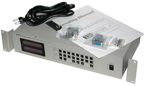
Unpacking It is neither complicated to install nor difficult to operate your Video Audio Matrix Switcher. However, a few minutes of your time are required to read this manual for a properly wired installation and to become familiar with its many features. Please take great care in unpacking your set and do not discard the carton and other packing. They may be needed if it ever becomes necessary to return your set for servicing. Never place the unit near radiators, in front of heating vents, in direct sun light, in excessive humidity or dusty locations so as to avoid early damage and to provide years of quality use. Connect your complimentary components as illustrated in the following pages. Definition VMS-8 x 8 is a full matrix switcher which can represent 8 A/V inputs to any 8 A/V outputs simultaneously without any A/V thermal noise. This machine includes microprocessor controller, so its easy to control and it allows to be displayed the present setting at STATUS WINDOW DISPLAY. Besides PC can control the matrix system by RS-232 communication interface. In addition two 8 x 8 may be cascaded for control via a signal port by configuring one 8 x 8 as a MASTER. |
Features - VMS-8x8 A/V matrix switcher. - Simple and simultaneous output and disconnection function. - Audio/Video random control function. - Low crosstalk and wideband frequency response. - Parallel connection. - RS-232C interface. - Restore to the first setup mode in case of power failure. - Vertical interval switching function with GENLOCK in channel changing. - Lock function for protecting a configuration from users mishandling. |
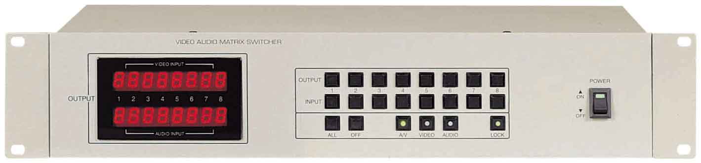
Front Panel Controls 1. POWER SWITCH Power ON/OFF switch. 2. OUTPUT SELECT SWITCH Selects output channel. When this button is pressed, the status of the selected channel is blinked. During the blinking select any input channels, then the status of display is changed as the selected input channel and the blinking is stopped. If the selection doesn't exist for 10 seconds approximately, the selection is canceled. 3. INPUT SELECT SWITCH Represents the selected input channel to each output channel. 4. ALL SWITCH Selects all output channels. Press this button, and the status display of all channels are blinked. If the selection doesn't exist for 10 seconds approximately, the selection is cancel. This function is very useful when one input is displayed to all outputs or when user wants to disconnect all outputs. 5. OFF SWITCH This button disconnects an output channel. If user press this button after select the OUTPUT SELECTING BUTTON, the selected status display indicate 0 and the output is nothing. 6. LOCK SWITCH Switch for protecting a configuration from mishandling. After the setting is completed, press this button 5 times then the light of this switch is blinked and all buttons cant be controlled. If user want to cancel this function, just press this button 5 times then the light is off. Lock function isn't cancel. Even if this machine is on and off. 7. STATUS DISPLAY (VIDEO) Displays the video configuration. The figure of status display represents which video inputs are transferred to video output terminals. 8. STATUS DISPLAY (AUDIO) Displays the audio configuration. The figure of status display represents which audio inputs are transferred to audio output terminals. 1~8 indicate each channel and & 0; means non output. 9. IN/OUT SELECT SWITCH MODE (A/V, VIDEO, AUDIO) Represents the setting condition of 2, 3 select switch. - A/V: 2, 3 select switches can control VIDEO and AUDIO signals. - VIDEO: 2, 3 select switches can control only VIDEO signals. - AUDIO: 2, 3 select switches can control only AUDIO signals. |
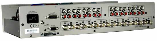
REAR PANEL CONTROLS |
1. VIDEO INPUT Input 1~8 video signals. 2. VIDEO OUTPUT Output the selected video signals in the control board of the front panel. 3. AUDIO INPUT Input 1~8 L,R audio signals. 4. AUDIO INPUT Output the selected audio signals in the control board of the front panel. 5. SELECT IN/OUT JACK Allows to be connected as parallel mode. PIN NO. SIGNAL FUNCTION 1 SEL A INPUT * Binary input for external control 2 SEL B INPUT 3 SEL C INPUT 4 SEL D INPUT 5 SEL E INPUT 6 GND GND 7 GND GND 8 V-SYNC OUTPUT Vertical sync output 9 SEL A OUTPUT * Binary output for external control 10 SEL B OUTPUT 11 SEL C OUTPUT 12 SEL D OUTPUT 13 SEL E OUTPUT 14 GND GND 15 GND GND 6. RS-232C JACK It allows to be connected PC with 8 x 8 by RS-232 communication port. Its possible to control VMS-8x8 by PC. RS-232C output terminal PIN NO. SIGNAL FUNCTION 1 NC 2 RXD RS-232C TERMINAL 3 TXD RS-232C TERMINAL 4 GND GND 5 GND GND 6 NC 7 NC 8 NC 9 NC 7. ~AC INPUT Power source input. |
RS-232C Operation - PROTOCOL RS-232C-STANDARD START BIT: 1 BIT STOP BIT: 1 BIT DATA BIT: 8 BIT PARITY BIT: NONE DATA RATE: 9600 BPS CODE: ASCII TERMINATE Installation 1. CONNECTION OF VIDEO DEVICES Video inputs and outputs may be connected to the BNC type connectors located on the rear panel of VMS-8x8. 2. CONNECTION OF AUDIO DEVICES Audio inputs and outputs may be connected to the RCA type connectors located on the rear panel of VMS-8x8. L and R of the RCA type connectors need to be connected exactly. |
Using the Matrix - POWERING THE MACHINE Connect the AC CORD which is involved in the carton box with the ~AC INPUT located on the rear of the machine. Plug the AC CORD to the power source (AC 110V, 50/ 60 Hz ), then turn on the power switch located on the front panel of VMS-8x8. If the connection is correct, the green light of power switch will be turned on. - USING THE CONTROL SWITCH ON THE FRONT PANEL 1. SELECTING AN OUTPUT To select an output, press one of the number of OUTPUT switch button. For example, to select output NO1, press output switch button NO1 of the front panel. At this time, status display NO1 located on left of the front panel is blinked for 10 seconds approximately. Like this, any outputs can be selected. These buttons correspond to output connectors as marked on the rear panel of VMS-8x8. 2. SELECTING AN INPUT To select an input, press one of the number of INPUT switch button. For example, to indicate input NO1 to output NO1, press output switch button NO1 and select input switch button NO1 when status display NO1 is blinked. Then the blinking of the status display is stopped and input NO1 is selected. These buttons correspond to input connectors as marked on the rear panel of the machine. 3. SELECTING A VIDEO Only to control a video, press VIDEO switch button. Confirm that the green light of the video switch button is turned on. 4. SELECTING A AUDIO Only to control a audio, press AUDIO switch button. Confirm that the green light of the audio switch button is turned on. 5. SELECTING A VIDEO/AUDIO To control a video and audio simultaneously, press A/V switch button. Confirm that the green light of the A/V switch button is turned on. |
6. USING THE ALL FUNCTION To control all outputs simultaneously, press the ALL switch button. For example, to display all output to input NO1, press the ALL switch button. Confirm that all status display are blinked. After that, press input NO1. Then the blinking is stopped and all status display indicate NO1. 7. USING THE OFF FUNCTION VMS-8x8 has a function that disconnects each output or all outputs. For example, To disconnect output NO1, Press the OUTPUT switch button NO1 and press the OFF switch button when the status display NO1 is blinked. Like this, to disconnect all outputs, press the ALL switch button. Then press the OFF switch button when all status displays are blinked. 8. USING THE LOCK FUNCTION VMS-8x8 has a LOCK function to preserve a configuration from users mishandling. To lock this machine, press the LOCK switch button 5 times repeatedly, confirm that the green light of the LOCK switch button is turned on. To recall the unit, press the LOCK switch button 5 times, confirm that the green light of the LOCK switch button is turned off. - USING THE CONTROL TERMINAL OF THE REAR PANEL 1. CONNECTING PARALLEL WITH OTHER VMS-8x8 (MASTER AND SLAVE) It allows to be controlled slave VMS-8x8 which is connected parallel with master by external connection jack. The operations of master affects them of slave equally. First of all, Make the cable which can connect IN/OUT SELECT of the rear panel using 15P D-SUB jack (figure 1). After connecting two matrix systems with cable, confirm that the operation of MASTER and the operation of SLAVE is the same when master is controlled. |
2. PARALLEL CONNECTION Two VMS-8x8 can be connected as two masters by connecting external jack each other. First of all, Make the cable which can connect IN/OUT SELECT of the rear panel using 15P D-SUB jack (figure 2) After connecting two matrix systems with cable, confirm that two VMS-8x8 operate as MASTER which can control other machine. |
3. CONNECTING WITH PC Its possible to control VMS-8x8 by PC with control program (RS-232C communication interface) First of all, make the cable which can connect PC using 9P D-SUB jack. Then connect VMS-8x8 with PC using the cable. And execute the control program in PC. Confirm that the operation of PC and the operation of VMS-8x8 is the same when PC is controlled (figure 3) |
| CONNECTIONS |
Block Diagram |
Specifications - ELECTRICAL VIDEO Input/Output Signal Level ..............................................................................................1 Vp-p 140 IRE Input/Output Impedance ..............................................................................................................75. Input/Output Connector .....................................................................................Composite Video BNC Frequency Response (7 MHz) ..........................................................................................Below ± 0.5dB S/N.........................................................................................................................................-60 dB Crosstalk ..................................................................................................................................-60 dB AUDIO Input/Output Signal Level/Impedance .............................................2.2 Vp-p/High Impedance Unbalance Input/Output Connector................................................................................................................RCA T.H.D+N (20 Hz~20 kHz) ....................................................................................................Below 0.1% Frequency Response (20 Hz~20 kHz) ...................................................................................Below ± 3 dB S/N ...............................................................................................................................Above 90 dB Crosstalk .........................................................................................................................Below -90 dB CONTROL CPU................................................................................................................................KS88C4632 Interface ...............................................................................................................................RS-232C Data Bit ......................................................................................................................................8 bit Stop Bit ......................................................................................................................................1 bit Parity...............................................................................................................................None Parity - GENERAL Power Source ................................................................................................AC 110 V, 50/ 60 Hz Dimensions .................................................................................................482(W) 88(H) 220(D)mm ..................................................................................................................19" wide, 9.5" deep, 3.5" high. * Specifications and design subject to change without notice for improvements. |
 |
 |
 |
 |