|
|
|
||||||||||||||||||||||||||||||||
 |
|
||||
|
|
|||||||||||
See Related items. |
See Manual. |
See Pictures |
See all Pan Tilts on one page.
|
||
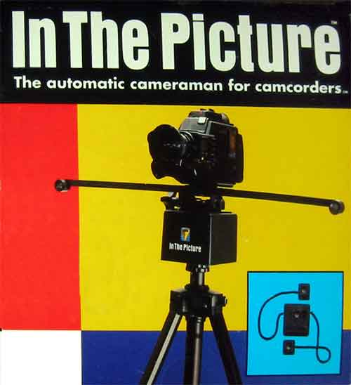 |
In
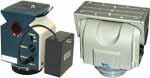
The Picture The automatic cameraman for camcorders. Operating Manual |
 |
UNPACKING
The following items are included in the packaging: In The Picture
Tracking Unit In The Picture Transmitter Product Registration Card Operating Manual Read and save these operating instructions. |
|||
OWNERS
RECORD Record serial numbers here for future reference. Serial numbers are located in- side the battery compartments of the In The Picture Tracking Unit and Main |
BUTTONS |
|
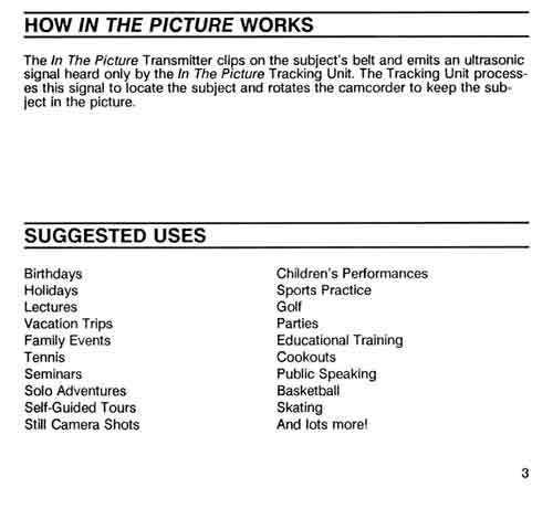 |
HOW IN
THE PICTURE WORKS The In The Picture Transmitter clips on the subjects belt and emits an ultrasonic signal heard only by the In The Picture Tracking Unit. The Tracking Unit processes this signal to locate the subject and rotates the camcorder to keep the subject in the picture. |
SUGGESTED
USES Birthdays Children&;s Performances Holidays Sports Practice Lectures Golf Vacation Trips Parties Family Events Educational Training Tennis Cookouts Seminars Public Speaking Solo Adventures Basketball Self-Guided Tours Skating Still Camera Shots And lots more! 3 |
|
 |
TRACKING
UNIT Ultrasonic Receiver Ultrasonic Receiver Tracking Indicator Light (Red). Power/Mode Indicator Light (Green) Power Switch Light Power/Mode Indicator Light (Green)TRACKING UNIT 4 |
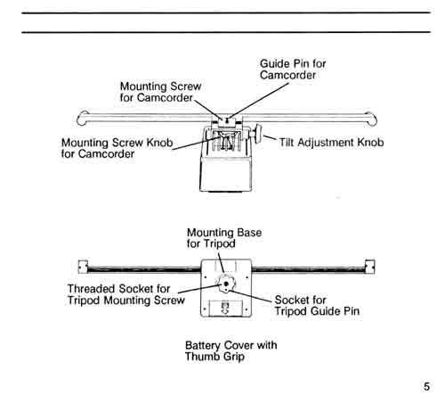 |
Mounting Screw for Camcorder Guide Pin for Camcorder Mounting Screw for Camcorder Tilt Adjustment Knob Mounting Base for Tripod Threaded Socket for Tripod Mounting Screw Socket for Tripod Guide Pin Battery Cover with Thumb Grip 5 |
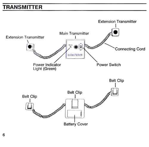 |
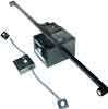
TRANSMITTER Extension Transmitter Main Transmitter Extension Transmitter Connecting Cord Power Indicator Light (Green) Power Switch Belt Clip Battery Cover 6 |
|||
 |
SPECIAL
FEATURES CONTINUOUS PANNING Tracks the action anywhere within a 35 foot radius without obstructions. SMART-TRACK MOTION CONTROL PROCESSOR Keeps camera motion smooth and natural. Can be set to different speeds for different activities. RUGGED CONSTRUCTION Durable ABS Plastic lets in The Picture go where your camcorder goes. UNIVERSAL CAMCORDER AND TRIPOD ATTACHMENTS To easily fit any camcorder and tripod. 7 |
|||
 |
INSTALLING
AND REPLACING BATTERIES The Tracking Unit operates on 10 AA batteries. The Transmitter operates on one 9v battery. The Transmitter has a green Power Indicator Light which illuminates when power is on. The Tracking Unit has a green Power/Mode Indicator Light which displays 4 long flashes when unit is initially turned on. These flashes are normal and are used to set the unit&;s operating mode as described on p.18 of this manual. A steadily flashing Power/Mode Indicator Light on the Tracking Unit indicates batteries are low and should be replaced. When In The Picture is not to be used for a long period of time, remove batteries to avoid damage caused by battery leakage and corrosion. 8 |
|
Tracking
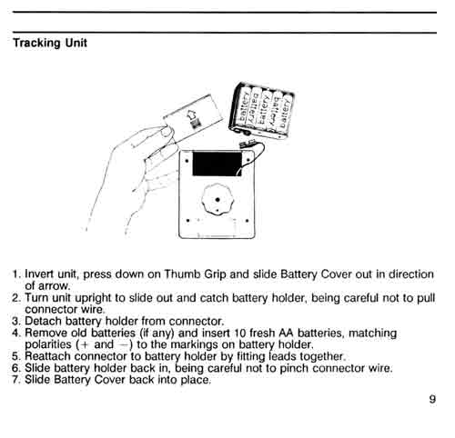
Unit 1. Invert unit, press down on Thumb Grip and slide Battery Cover out in direction of arrow. 2. Turn unit upright to slide out and catch battery holder, being careful not to pull connector wire. 3. Detach battery holder from connector. 4. Remove old batteries (if any) and insert 10 fresh AA batteries, matching polarities (+ and -) to the markings on battery holder. 5. Reattach connector to battery holder by fitting leads together. 6. Slide battery holder back in, being careful not to pinch connector wire. 7. Slide Battery Cover back into place. 9 |
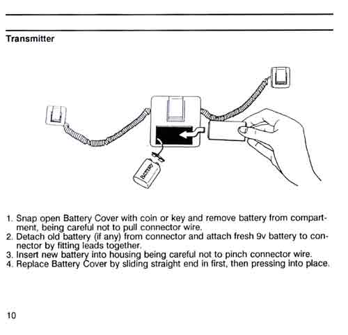 |
Transmitter 1. Snap open Battery Cover with coin or key and remove battery from compartment, being careful not to pull connector wire. 2. Detach old battery (if any) from connector and attach fresh 9v battery to connector by fitting leads together. 3. Insert new battery into housing being careful not to pinch connector wire. 4. Replace Battery Cover by sliding straight end in first, then pressing into place. 10 |
 |
HOW TO
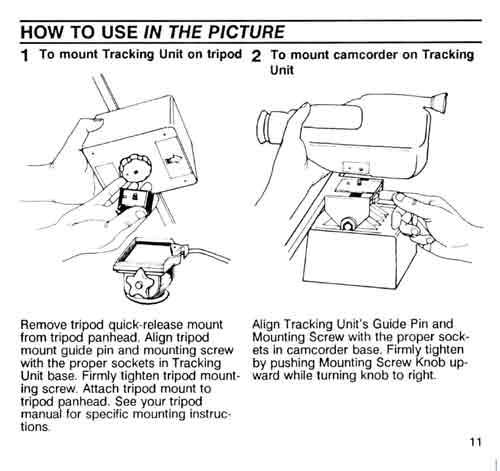
USE IN THE PICTURE 1. To mount Tracking Unit on tripod Remove tripod quick-release mount from tripod panhead. Align tripod mount guide pin and mounting screw with the proper sockets in Tracking Unit base. Firmly tighten tripod mounting screw. Attach tripod mount to tripod panhead. See your tripod manual for specific mounting instructions. 2. To mount camcorder on Tracking Unit Align Tracking Unit&;s Guide Pin and Mounting Screw with the proper sockets in camcorder base. Firmly tighten by pushing Mounting Screw Knob upward while turning knob to right. 11 |
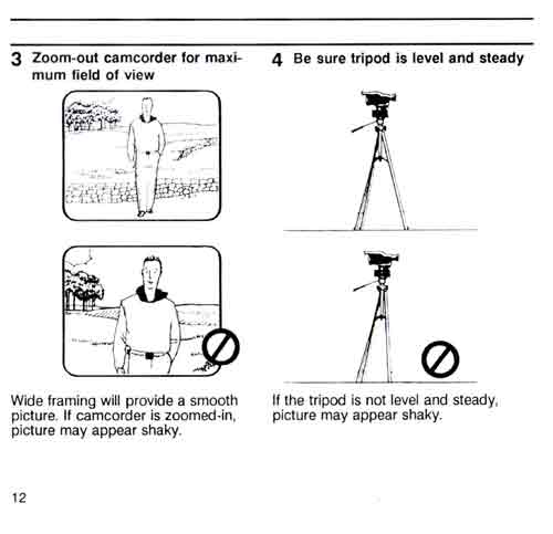 |
3. Zoom-out
camcorder for maximum field of view Wide framing will provide a smooth picture. If camcorder is zoomed-in, picture may appear shaky. 4. Be sure tripod is level and steady If the tripod is not level and steady, picture may appear shaky. 12 |
|||
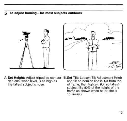 |
5. To adjust
framing for most subjects outdoors A. Set Height: Adjust tripod so camcorder lens, when level, is as high as the tallest subjects nose B. Set Tilt: Loosen Tilt Adjustment Knob and tilt so horizon line is 1/3 from top of frame, then tighten. (Or so tallest subject fills 80% of the height of the frame as shown when he or she is 10 feet away.) 13 |
|||
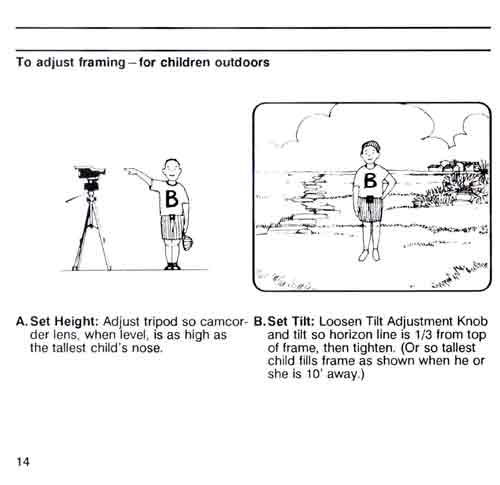 |
To adjust
framing for children outdoors A. Set Height: Adjust tripod so camcorder lens, when level, is as high as the tallest child's nose. B. Set Tilt: Loosen Tilt Adjustment Knob and tilt so horizon line is 1/3 from top of frame, then tighten. (Or so tallest child fills frame as shown when he or she is 10 feet away.) 14 |
 |
To adjust
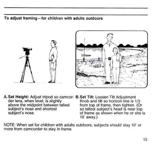
framing for children with adults outdoors A .Set Height: Adjust tripod so camcorder lens, when level, is slightly above the midpoint between tallest subjects nose and shortest subjects nose. B. Set Tilt: Loosen Tilt Adjustment Knob and tilt so horizon line is 1/3 from top of frame, then tighten. (Or so tallest subjects head is near top of frame as shown when he or she is 10 feet away.) NOTE: When set for children with adults outdoors, subjects should stay 10 feet or more from camcorder to stay in frame. 15 |
 |
To adjust
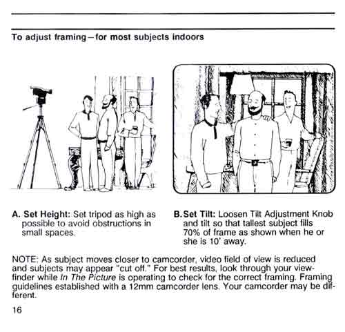
framing for most subjects indoors A. Set Height: Set tripod as high as possible to avoid obstructions in small spaces. B. Set Tilt: Loosen Tilt Adjustment Knob and tilt so that tallest subject fills 70% of frame as shown when he or she is 10 feet away. NOTE: As subject moves closer to camcorder, video field of view is reduced and subjects may appear cut off. For best results, look through your view- finder while In The Picture is operating to check for the correct framing. Framing guidelines established with a 12 mm camcorder lens. Your camcorder may be different. 16 |
|||
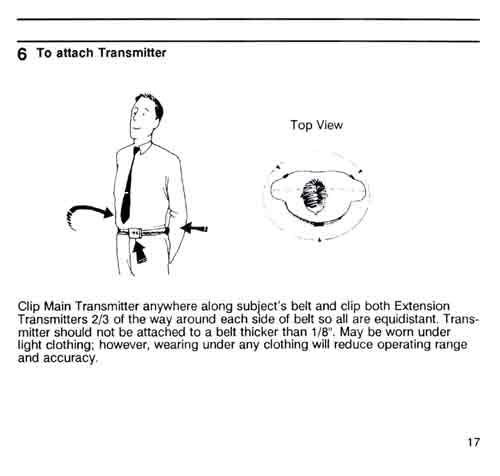 |
6. To attach
Transmitter Top View Clip Main Transmitter anywhere along subjects belt and clip both Extension Transmitters 2/3 of the way around each side of belt so all are equidistant. Transmitter should not be attached to a belt thicker than 1/8. May be worn under light clothing; however, wearing under any clothing will reduce operating range and accuracy. 17 |
|||
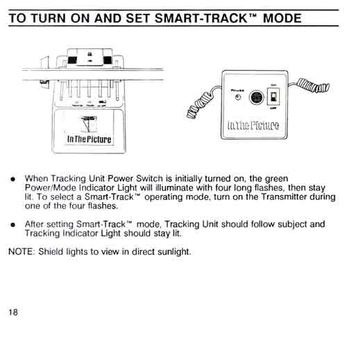 |
TO TURN
ON AND SET SMART-TRACK MODE When Tracking Unit Power Switch is initially turned on, the green Power/Mode Indicator Light will illuminate with four long flashes, then stay lit. To select a Smart-Track operating mode, turn on the Transmitter during one of the four flashes. After setting Smart-Track mode, Tracking Unit should follow subject and Tracking Indicator Light should stay lit. NOTE: Shield lights to view in direct sunlight. 18 |
|||
|
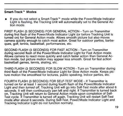
Smart-Track
Modes If you do not select a Smart-Track mode while the Power/Mode
Indicator Light is flashing, the Tracking Unit will automatically set
to the General Action mode. FIRST FLASH (5 SECONDS) FOR GENERAL ACTION- Turn on Transmitter during first flash of the Power/Mode Indicator Light (or before Tracking Unit is turned on) for General Action mode. Allows smooth picture but also moves camera quickly enough to catch most action. Great for outdoor parties, barbecues, golf, tennis, basketball, performances, etc. SECOND FLASH (3 SECONDS) FOR FAST ACTION- Turn on Transmitter during second flash of the Power/Mode Indicator Light for Fast Action mode. Allows camera to react more quickly and catch faster action than General Action mode, but picture motion may appear less smooth. Great for fast action basketball games, tennis, skating, etc. THIRD FLASH (3 SECONDS) FOR SLOW ACTION- Turn on Transmitter during third flash of the Power/Mode Indicator Light for Slow Action mode. Keeps picture motion the smoothest for lectures, public speaking, indoor parties, etc. FOURTH FLASH (3 SECONDS) FOR SELF-TEST MODE - If Transmitter is turned on for at least 1 second during fourth flash of the Power/Mode Indicator Light and then turned off, Tracking Unit will go into Self-Test mode after about 6 seconds. It will then continuously pan left and right. If Transmitter is turned back on, Tracking Unit will return to General Action mode upon completion of Self- Test cycle. If Transmitter is turned off again, Tracking Unit will restart Self-Test mode after about 6 seconds. During Self-Test, Power/Mode Indicator Light and Tracking Indicator Light do not function normally. 19 |
 |
||
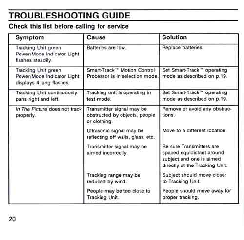
| TROUBLESHOOTING
GUIDE Check this list before calling for service. |
||
Symptom |
Cause |
Solution |
Tracking Unit
green Power/Mode Indicator Light flashes steadily. |
Batteries
are low. |
Replace batteries. |
Tracking Unit
green Power/Mode Indicator Light displays 4 long flashes. |
Smart-Track
Motion Control Processor is in selection mode. |
Set Smart-Track
operating mode as described on p.19. |
Tracking Unit
continuously pans right and left. |
Tracking unit
is operating in test mode. |
Set Smart-Track
operating mode as described on p.19. |
In The Picture
does not track properly. 20 |
Transmitter
signal may be obstructed by objects, people or clothing. Ultrasonic signal may be reflecting off walls, glass, etc. Transmitter signal may be aimed incorrectly. Tracking range may be reduced by wind. People may be too close to Tracking Unit. |
Remove or
avoid any obstruction. Move to a different location. Be sure Transmitters are spaced equidistant around subject and one is aimed directly at the Tracking Unit. Subject should move closer to Tracking Unit. People should move away for proper tracking. |
 |
||||||||||||||||||||||||
|
||||||||||||||||||||||||
|
HOW TO
CARE FOR IN THE PICTURE Keep out of water, mist, salt spray or extreme humidity. Avoid blowing sand or dirt. Keep out of hot spots such as car trunk. Store in a cool, dry place. Remove batteries when not in use. To clean use soft cloth slightly moistened with water or a mild detergent solution. Do not use cleaning fluids or aerosols because they could enter the unit and cause damage. Never open the casing or make any adjustments not described in this operating manual. 22 |
 |
|
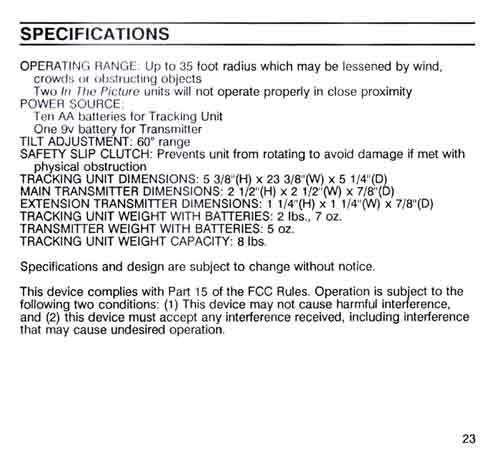
SPECIFICATIONS OPERATING RANGE: Up to 35 foot radius which may be lessened by wind, crowds or obstructing objects Two In The Picture units will not operate properly in close proximity POWER SOURCE: Ten AA batteries for Tracking Unit. One 9v battery for Transmitter TILT ADJUSTMENT: 60 degree range SAFETY SLIP CLUTCH: Prevents unit from rotating to avoid damage if met with physical obstruction TRACKING UNIT DIMENSIONS: 5 3/8(H) x 23 3/8(W) x 5 1/4(D) MAIN TRANSMITTER DIMENSIONS: 2 1/2(H) x 2 1/2(W) x 7/8(D) EXTENSION TRANSMITTER DIMENSIONS: 1 1/4(H) x 1 1/4(W) x 7/8(D) TRACKING UNIT WEIGHT WITH BATTERIES: 2 lbs., 7 oz. TRANSMITTER WEIGHT WITH BATTERIES: 5 02. TRACKING UNIT WEIGHT CAPACITY: 8 lbs. Specifications and design are subject to change without notice. This device complies with Part 15 of the FCC Rules. Operation is subject to the following two conditions: (1) This device may not cause harmful interference, and (2) this device must accept any interference received, including interference that may cause undesired operation. 23 |
|
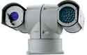
Pan Tilt
Zoom (PTZ) CCTV cameras are affordable and offer better performance
then ever. Pan Tilt Zoom surveillance cameras are used by Government, large corporations, casinos and consumers. Other uses include Mast Aerial Photography. PTZ cameras rotate horizontally through 360 degrees, vertically through 90 degrees and have motorized optical zoom lenses. A camera turret or a motorized swivel is similar to a pan-tilt head. Pan Tilt movement can be very fast and is controlled through a wired (or wireless) connection, by the mating controller. PTZ cameras are often mounted in domes, outside dome cameras are weatherproofed, heated and cooled. |
 |
 |
 |
 |