|
|
|
||||||||||||||||||||||||||||||||
 |
|
||||
|
|
|||||||||||
See Related items. |
Joystick Manual. |
Motor Manual. |
See all Pan Tilts on one page.
|
||
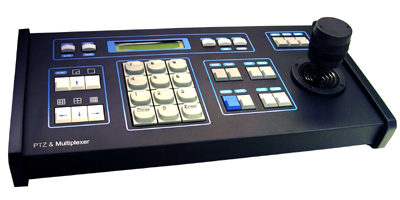  |
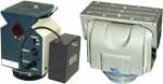
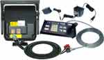
· 3-Axis Joystick and Keyboard Controller for Pan and Tilt motor. |
| Allows you to move the camera up & down, right & left over a wired hand held remote control. |
Specification Detail Signal System RS 485 Functions on Keyboard: PTZ Commands: CALL, PRESET, SHOT Camera Commands: WIDE/TELE , FAR/NEAR, CAM/ID, AUTO, OPEN/CLOSE Other Functions: ON/OFF, LIVE/TAPE, F1, F2, F3, SEQ/MUL Multiplexer view: FUNC/ Full Screen, 4x4, 2x2, 3x3, PIP Numbers: 1~9 and Clear/Enter Protocol: 1 Dipswitch set 1~8 Multiprotocol , Compatible with PELCO-D Protocol 2 sets of RS485 block connector 1 RJ11 RS485 Connector Baudrate Communication: 2400BPS, 4800BPS, 9600BPS, 19200BPS Communication Distance: 1200m - 3936Ft Power : DC12V 800mA Weight: 2Kg - 4Lbs Size: 380 x 165 x 80(mm) |
Speed Dome Camera Controller
Operation Manual
Please read this operation manual before using this device and use the device properly.
Also, please keep this manual with care to ensure easy access at any time.
| INDEX I. Summary II. Introduction of Function ...................................................................1 III. Introduction of the Keyboard's Panel ..............................................2 1 The sketch of the Front and Description of Buttons ............................2 2 Rear Panel ........................................................................................3 IV. Setting of the Keyboard .................................................................4 1 Setup of the Protocol and the Default Baud Rate ...............................4 2 Setup of the Baud Rate of Communication ........................................5 V. Operation of the Keyboard .............................................................6 VI. Installation and Connection ............................................................9 VII. Technical Specifications ..............................................................11 VIII. Points for Attention ....................................................................12 ROHS |
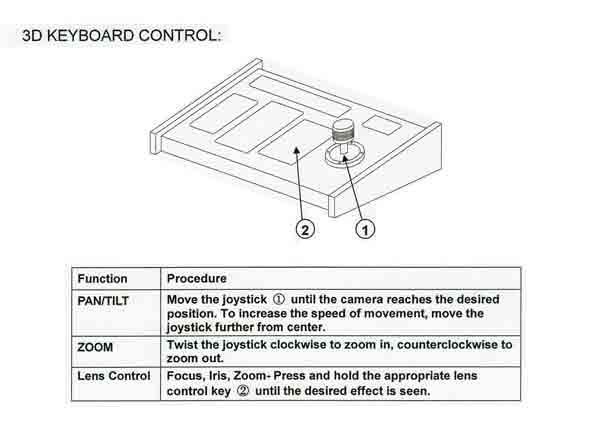
3D KEYBOARD CONTROL: Function and Procedure PAN/TILT Move the joystick (1) until the camera reaches the desired position. To increase the speed of movement, move the joystick further from center. ZOOM Twist the joystick clockwise to zoom in, counterclockwise to zoom out. Lens Control Focus, Iris, Zoom- Press and hold the appropriate lens control key (2) until the desired effect is seen. |
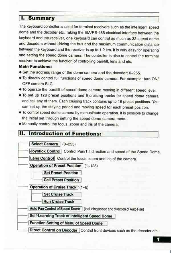
I. Summary
The keyboard controller is used for terminal receivers such as the intelligent speed dome and the decoder etc. Taking the EIA/RS-485 electrical interface between the keyboard and the receiver, one keyboard can control as much as 32 speed dome and decoders without driving the bus and the maximum communication distance between the keyboard and the receiver is up to 1.2 km. It is very easy for operating and setting the speed dome camera. The controller is also to control the terminal receiver to achieve the function of controlling pan/tilt, lens and etc.
Main Functions:
• Set the address range of the dome camera and the decoder: 0-255.
• To directly control full functions of speed dome camera. For example: turn ON/ OFF camera BLC.
•To operate the pan/tilt of speed dome camera moving in different .speed level ^ To set up 128 preset positions and 6 cruising tracks for speed dome camera
and call any of them. Each cruising track contains up to 16 preset positions. You
can set up the staying period and moving speed for each preset position.
• To control speed dome camera by manual/auto operation. It is possible to change
the initial set through setting the speed dome camera menu.
• Manually control the focus, zoom and iris of the camera.
11. Introduction of Functions:
Select Camera I (0~255)
Joystick Control Control Pan/Tilt direction and speed of the Speed Dome.
Lens Controll Control the focus, zoom and iris of the camera.
Operation of Preset Position (1-128)
Set Preset Position
Call Preset Position
Operation of Cruise Track (1-6)
Set Cruise Track
Run Cruise Track
Auto Pan Control of Speed Dome I (including speed and direction of Auto Pan)
Self-Learning Track of Intelligent Speed Dome
Function Setting of Menu of Speed Dome
Direct Control on Decoder I Control front devices such as the decoder etc.
Page 01
III. Introduction of the keyboard Panel • CALL: To call the preset position.
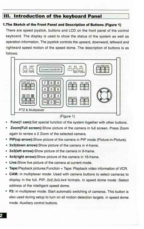
1.The Sketch of the Front Panel and Description of Buttons (Figure 1) There are speed joystick, buttons and LCD on the front panel of the control
keyboard. The display is used to show the status of the system as well as operation information. The joystick controls the upward, downward, leftward and
rightward speed motion of the speed dome. The description of buttons is as follows:
(Figure 1)
• Func(1 cam):Set special function of the system together with other buttons.
• Zoom(Full screen):Show picture of the camera in full screen. Press Zoom
again to review a 2 Zoom of the selected camera.
• PIP(up arrow):Show picture of the camera in PIP mode (Picture-in-Picture).
• 2x2(down arrow):Show picture of the camera in 4-frame.
• 3x3(left arrow):Show picture of the camera in 9-frame.
• 4x4(right arrow):Show picture of the camera in 16-frame.
• Live:Show live picture of the camera at current mode.
• Tape:Playback pictures: Function + Tape: Playback video information of VCR.
• CAM: in multiplexer mode: Used with camera buttons to select cameras to
display in the full, PIP; 2x2,3x3,4x4 formats. in speed dome mode :Select address of the intelligent speed dome.
• F2: in multiplexer mode: Start automatic switching of cameras. This button is
also used during setup to turn on all motion detection targets. in speed dome mode :Auxiliary control buttons.
Page 02
• CALL: To call the preset position.
• PRESET: To set the preset position.
• SHOT: To set up or call cruising track.
• AUTO: To control auto-horizontal rotation for pan/tilt.
• WIDE: To a wide angle.
• TELE: To turn to a telescopic range.
• FAR: To make focus far manually.
• NEAR: To make focus near manually.
• OPEN: To open iris.
• CLOSE: To close iris.
• ON: Switch on the setting of function.
• OFF: Switch off the setting of function.
• F1: Auxiliary control buttons.
• F3: Switching control between intelligent speed dome and multiplexer.
• [0]-[9]: Number key
• [Clear]: To clear inputted data
• [Enter]: To confirm
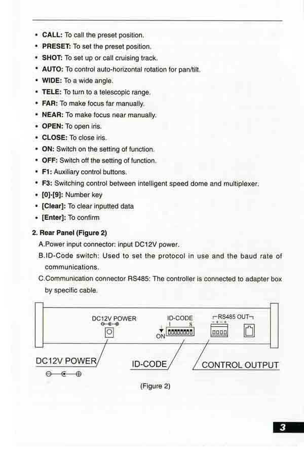
2. Rear Panel (Figure 2)
A. Power input connector: input DC12V power.
B.ID-Code switch: Used to set the protocol in use and the baud rate of communications.
C.Communication connector RS485: The controller is connected to adapter box by specific cable.
(Figure 2)
Page 03
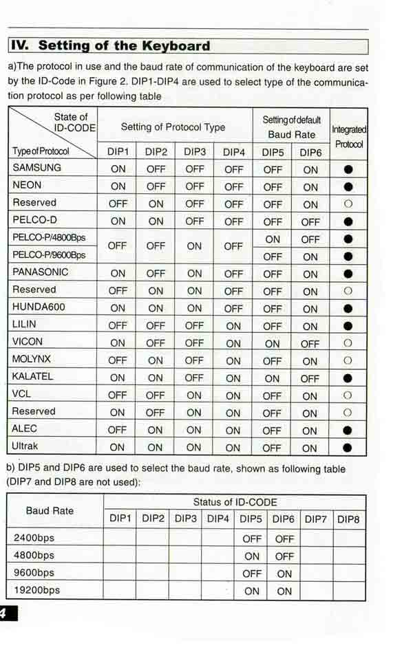
IV. Setting of the Keyboard
a)The protocol in use and the baud rate of communication of the keyboard are set by the ID-Code in Figure 2.
DIP1-DIP4 are used to select type of the communication protocol as per following table
State of Setting of Protocol Type Integrated
ID-CODE Setting of default Protocd
Type of Protocol Baud Rate
DIP1 DIP2 DIP3 DIP4 DIP5 DIP6
SAMSUNG ON OFF OFF OFF OFF ON •
NEON ON OFF OFF OFF OFF ON •
Reserved OFF ON OFF OFF OFF ON 0
PELCO-D ON ON OFF OFF OFF OFF •
PELCO-P/4800Bps OFF OFF ON OFF ON OFF •
PELCO-P/9600Bps OFF ON •
PANASONIC ON OFF ON OFF OFF ON •
Reserved OFF ON ON OFF OFF ON 0
HUNDA600 ON ON ON OFF OFF ON •
LILIN OFF OFF OFF ON OFF ON •
VICON ON OFF OFF ON ON OFF 0
MOLYNX OFF ON OFF ON OFF ON 0
KALATEL ON ON OFF ON ON OFF •
VCL OFF OFF ON ON OFF ON 0
Reserved ON OFF ON ON OFF ON 0
ALEC OFF ON ON ON OFF ON •
Ultrak ON ON ON ON OFF ON •
b) DIP5 and DIP6 are used to select the baud rate, shown as following table (DIP7 and DIP8 are not used):
Status of ID-Code Baud Rate |
DIP1 |
DIP2 |
DIP3 |
DIP4 |
DIP5 |
DIP6 |
DIP7 |
DIP8 |
2400bps |
|
|
|
|
OFF |
OFF |
|
|
4800bps |
|
|
|
|
ON |
OFF |
|
|
9600bps |
|
|
|
|
OFF |
ON |
|
|
19200bps |
|
|
|
|
ON |
ON |
|
|
Page 04
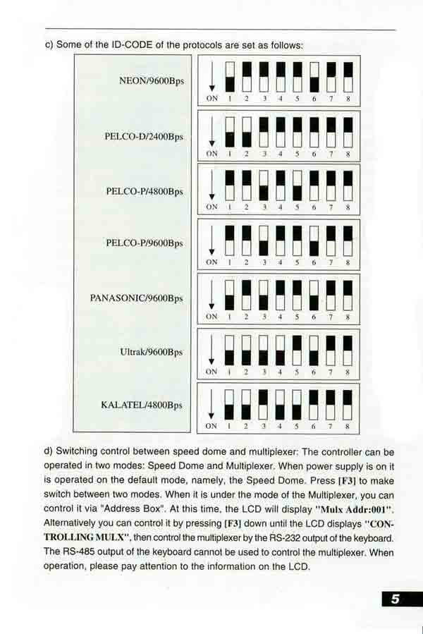
c) Some of the ID-CODE of the protocols are set as follows:
NEON/9600Bps
PELCO-D/2400Bps
PELCO-P/4800Bps
PELCO-P/9600Bps
PANASONIC/9600Bps
Ultrak/9600Bps
KALATEL/4800Bps
d) Switching control between speed dome and multiplexer: The controller can be operated in two modes: Speed Dome and Multiplexer. When power supply is on it is operated on the default mode, namely, the Speed Dome., Press [F3] to make
switch between two modes. When it is under the mode of the Multiplexer, you can
control it via "Address Box". At this time, the LCD will display "Mulx Addr:001". Alternatively you can control it by pressing [F3] down until the LCD displays "CON- TROLLING MULX", then control the multiplexer by the RS-232 output of the keyboard.
The RS-485 output of the keyboard cannot be used to control the multiplexer. When operation, please pay attention to the information on the LCD.
Page 05
V. Operation of the Keyboard
1. Select Address of the Speed Dome Camera: [CAM]+[N]+[Enter]
Display: Current CamID: 001
Description: N -- No. of camera from 0 to 255
Function: Select the address of the camera to be controlled. When the value N is in conformity with the address of the Speed Dome Camera, it will be under control.
2. Set the Preset Position: [PRESET]+[N]+[ Enter]
Display: Preset No: 001
Description: N -- No. of preset position from 1 to 128.
Function: Store current position and refer it as No. N position.
3. Call the Preset Position: [CALL]+[N]+[ Enter]
Display: Call Number: 001
Description: N -- No. of preset position from 1 to 128.
Function: Transfer the camera to the position of No. N preset position.
4. Cancel the Preset Position: [PRESET]+[N]+[OFF]
Display: Preset No: 001
Description: N -- No. of preset position from 1 to 128.
Function: Delete the No. N preset position stored.
5. Set the Cruise Track (NEON, SAMSUNG, PELCO-D, PELCO-P Available):
• Enter the Status of Track Setting[SHOT]+[N]+[ON] (N£°No. of track from 1 to 6). Display: Track = 01 Sum = 06
Description: Track No.1 is currently setting, in which there are 6 preset points.
• Edit Track: Press [TELE] to edit down page and press [WIDE] to edit up page. Each track involves 16 preset points and the running speed and the dwelling time of each preset position.
Display: No.: 01 Point: 001 -> Description: The 1st preset position in the track is001.
Display: No.: 01 Speed: 001 -* Description: The speed of the 1st preset point in the track is the 1st class.
Display: No.: 01 Time: 004 -* Description: The dwelling time of the 1st preset point in the track is 4 seconds
• Speed Range: 1 to 8 from the fastest to the lowest. Any speed outside the range
will be referred as the 1st class; the range of the dwelling time is: 1 to 255.
• When the No. N preset point is set as No. 0, then all preset points before the No.
N preset point in the track will be valid however all numbers of preset points afterward and their speed and dwelling time shall be set as 0 automatically.
• After tracks are edited, press OFF to store and exit while push the joystick to exit without storage.
Page 06
6. Run Cruise Track: [SHOT]+[N]+ [Enter]
Display: Input Tour No: 01
Description: N -- No. of the track from 1 to 6.
Function: Tour the No. N track and stop tour by pushing the joystick.
7. Stop Cruise Track: [SHOT]+[N]+ [OFF]
Display: Input Tour No: 01
Description: N -- No. of the track from 1 to 6.
Function: Stop the No. N track or stop tour by pushing the joystick.
8. Cancel Cruise Track: [SHOT]+[N]+ [OFF] (Pressing [OFF] down until " Clear Tour OK "appears)
Display: Input Tour No: 01
Description: N -- No. of the track from 1 to 6.
Function: Delete the No. N track
9. Auto Pan ON (Operation of NEON, SAMSUNG Protocol): [AUTO]+[P1]+[ON]+ [P2]+[OFF]
Display: Input 1st No: 001
Description: P1---- the starting scan No. of preset point from 1 to 128, which should be set already.
Display: Input 2nd No: 002
Description: P2---- the ending scan No. of preset point from 1 to 128, which should be set already.
If P1 = P2 or P1 and P2 are coincided, the speed dome will make scan in range of 360°
Note:
(1) For PELCO-D and PELCO-P Protocols the way of operation is as follows:
• Set the Starting Scan Position: Transfer the speed dome to the starting scan position, operation [AUTO]+[ON]
• Set the Ending Scan Position: Transfer the speed dome to the ending scan positioh, operation [AUTO]+[OFF]
• Run Auto Pan: [AUTO]+[ENTER]
(2) Auto Pan operation takes the following parameters. You must set these
Page 07
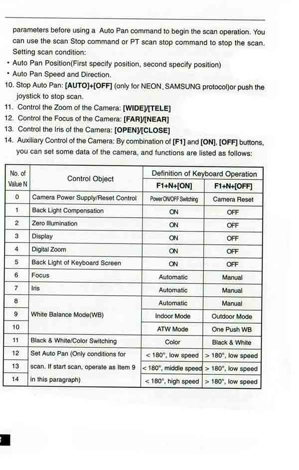
parameters before using a Auto Pan command to begin the scan operation.
You can use the scan Stop command or PT scan stop command to stop the scan. Setting scan condition:
• Auto Pan Position(First specify position, second specify position)
• Auto Pan Speed and Direction.
10. Stop Auto Pan: [AUTO]+[OFF] (only for NEON,SAMSUNG protocol)or push the joystick to stop scan.
11. Control the Zoom of the Camera: [WIDE]/[TELE]
12. Control the Focus of the Camera: [FAR]/[NEAR]
13. Control the Iris of the Camera: [OPEN]/[CLOSE]
14. Auxiliary Control of the Camera: By combination of [Fl] and [ON], [OFF] buttons, you can set some data of the camera, and functions are listed as follows:
No. of |
Control Object |
||
Definition of Keyboard Operation |
|||
F1+N+[ON] |
F1+N+[OFF] |
||
0 |
Camera Power Supply/Reset Control |
Power ON /OFF Swiching |
Camera Reset |
| 1 | Back Light Compensation | ON |
OFF |
2 |
Zero Illumination |
ON |
OFF |
| 3 | Display |
ON |
OFF |
4 |
Digital Zoom |
ON |
OFF |
5 |
Back Light of Keyboard Screen |
ON |
OFF |
6 |
Focus |
Automatic |
Manual |
7 |
Iris |
Automatic |
Manual |
8 |
White Balance Mode(WB) Automatic Manual | Automatic |
Manual |
9 |
Indoor Mode |
Outdoor Mode |
|
10 |
ATW Mode |
One Push WB |
|
11 |
Black & White/Color Switching | Color |
Black & White |
12 |
Set Auto Pan (Only conditions for scan. |
< 180°, low speed |
> 180°, low speed |
13 |
< 180°, middle speed |
> 180°, low speed |
|
14 |
< 180°, high speed |
> 180°, low speed |
|
Page 08
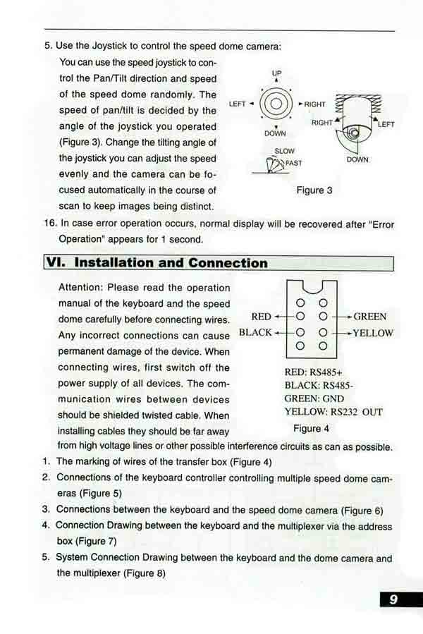
5. Use the Joystick to control the speed dome camera:
You can use the speed joystick to control the Pan/Tilt direction and speed of the speed dome randomly. The speed of pan/tilt is decided by the angle of the joystick you operated (Figure 3). Change the tilting angle of the joystick you can adjust the speed evenly and the camera can be focused automatically in the course of scan to keep images being distinct.
Figure 3
6. In case error operation occurs, normal display will be recovered after "Error
Operation" appears for 1 second.
VI. Installation and Connection
Attention: Please read the operation
manual of the keyboard and the speed
dome carefully before connecting wires. RED Any incorrect connections can cause BLACK
permanent damage of the device. When connecting wires, first switch off the power supply of all devices. The communication wires between devices should be shielded twisted cable. When installing cables they should be far away
from high voltage lines or other possible interference circuits as can as possible.
RED: RS485+
BLACK: RS485-
GREEN: GND
YELLOW: RS232 OUT
Figure 4
1. The marking of wires of the transfer box (Figure 4)
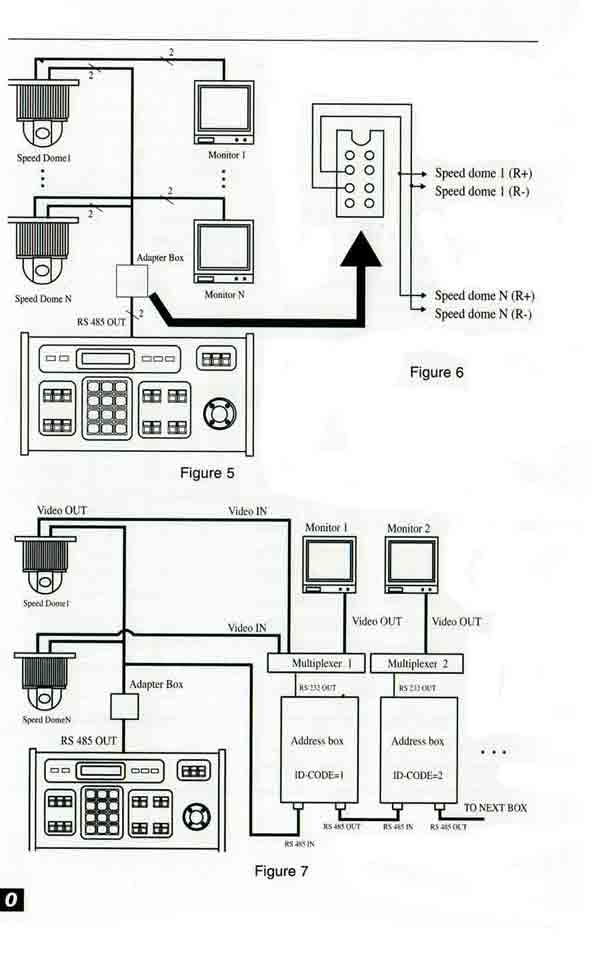
2. Connections of the keyboard controller controlling multiple speed dome cameras (Figure 5)
3. Connections between the keyboard and the speed dome camera (Figure 6)
4. Connection Drawing between the keyboard and the multiplexer via the address
box (Figure 7)
5. System Connection Drawing between the keyboard and the dome camera and
the multiplexer (Figure 8)
Page 09
Adapter Box
Figure 5
Multiplexer
Speed dome 1 (R+) Speed dome 1 (R-)
Speed dome N (R+) Speed dome N (R-)
Figure 6
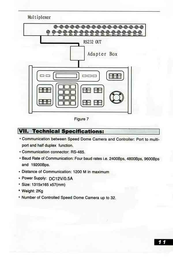
RS232 OUT
Adapter Box
Video OUT Video IN
EXT BOX
Figure 7
Page 10
VII. Technical Specifications:
• Communication between Speed Dome Camera and Controller: Port to multi-
port and half duplex function.
• Communication connector: RS-485.
• Baud Rate of Communication: Four baud rates i.e. 2400Bps, 4800Bps, 9600Bps
and 19200Bps.
• Distance of Communication: 1200 M in maximum • Power Supply: DC12V/0.5A
• Size: 315 x 165 x 57(mm), 12.5 x 6 x 2.5 inches.
• Weight: 2Kg, 4.5 pounds
• Number of Controlled Speed Dome Camera up to 32.
Page 11
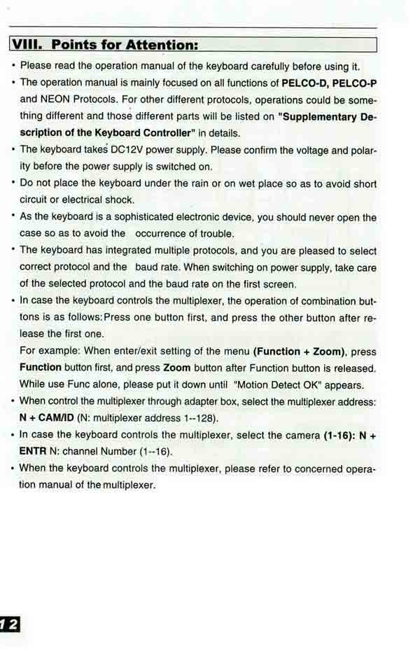
VIII. Points for Attention:
• Please read the operation manual of the keyboard carefully before using it.
• The operation manual is mainly focused on all functions of PELCO-D, PELCO-P and NEON Protocols. For other different protocols, operations could be something different and those different parts will be listed on "Supplementary Description of the Keyboard Controller" in details.
• The keyboard takes DC12V power supply. Please confirm the voltage and polarity before the power supply is switched on.
• Do not place the keyboard under the rain or on wet place so as to avoid short circuit or electrical shock.
• As the keyboard is a sophisticated electronic device, you should never open the case so as to avoid the occurrence of trouble.
• The keyboard has integrated multiple protocols, and you are pleased to select correct protocol and the baud rate. When switching on power supply, take care of the selected protocol and the baud rate on the first screen.
• In case the keyboard controls the multiplexer, the operation of combination buttons is as follows: Press one button first, and press the other button after release the first one.
For example: When enter/exit setting of the menu (Function + Zoom), press Function button first, and press Zoom button after Function button is released. While use Func alone, please put it down until "Motion Detect OK" appears..
• When control the multiplexer through adapter box, select the multiplexer address: N + CAM/ID (N: multiplexer address 1--128).
• In case the keyboard controls the multiplexer, select the camera (1-16): N + ENTR N: channel Number (1--16).
• When the keyboard controls the multiplexer, please refer to concerned operation manual of the multiplexer.
Page 12
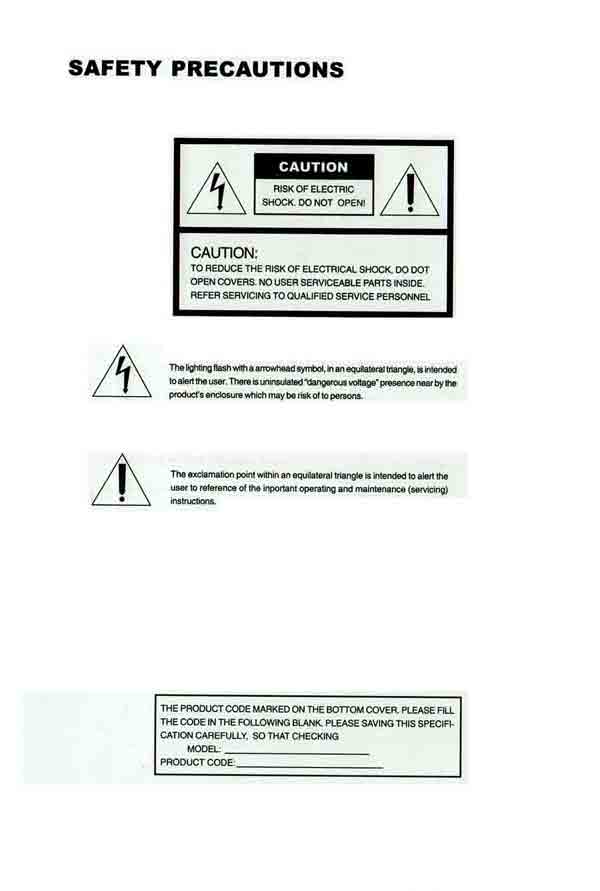
SAFETY PRECAUTIONS
RISK OF ELECTRIC SHOCK. DO NOT OPEN!
CAUTION:
TO REDUCE THE RISK OF ELECTRICAL SHOCK, DO DOT OPEN COVERS. NO USER SERVICEABLE PARTS INSIDE. REFER SERVICING TO QUALIFIED SERVICE PERSONNEL
The lighting flash with a arrowhead symbol, in an equilateral triangle, is intended to alert the user. There is uninsulated "dangerous voltage" presence nearby the product's enclosure which maybe risk of to persons.
The exclamation point within an equilateral triangle is intended to alert the
user to reference of the inportant operating and maintenance (servicing) instructions.
THE PRODUCT CODE MARKED ON THE BOTTOM COVER. PLEASE FILL THE CODE IN THE FOLLOWING BLANK. PLEASE SAVING THIS SPECIFICATION CAREFULLY, SO THAT CHECKING
 |
 |
 |
 |