|
|
|
||||||||||||||||||||||||||||||||
 |
|
||||
|
|
|||||||||||
See Related items. |
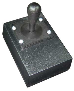
Joystick Manual. |
Motor Manual. |
See all Pan Tilts on one page.
|
||
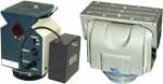
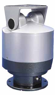
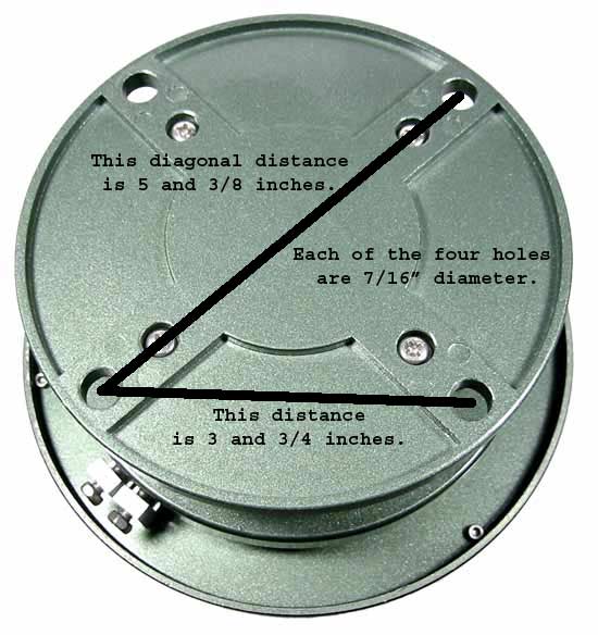
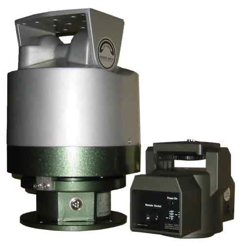
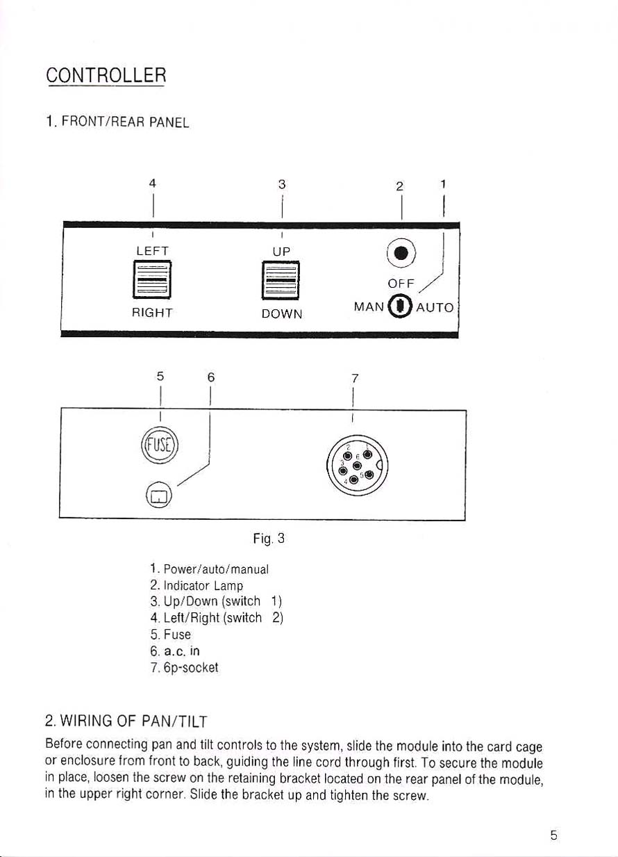
Model # PT1000n
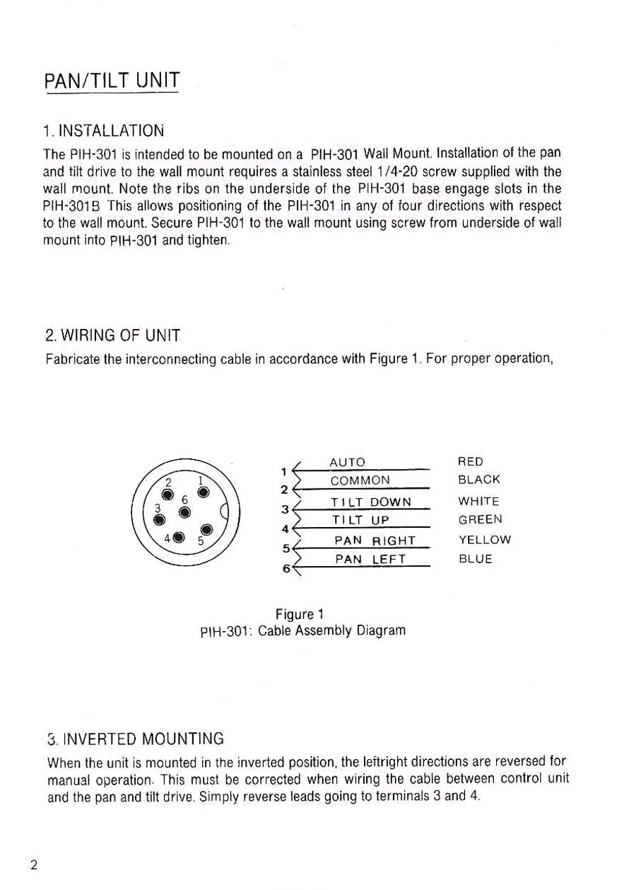
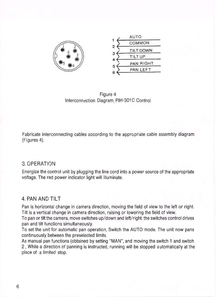
Weather proof, indoor or outdoor, motorized pan & tilt system. The connector on the current pan tilt head is a rectangular inline 6 conductor connector. Accommodates a 20 pound load (center of gravity at 2"above plate). 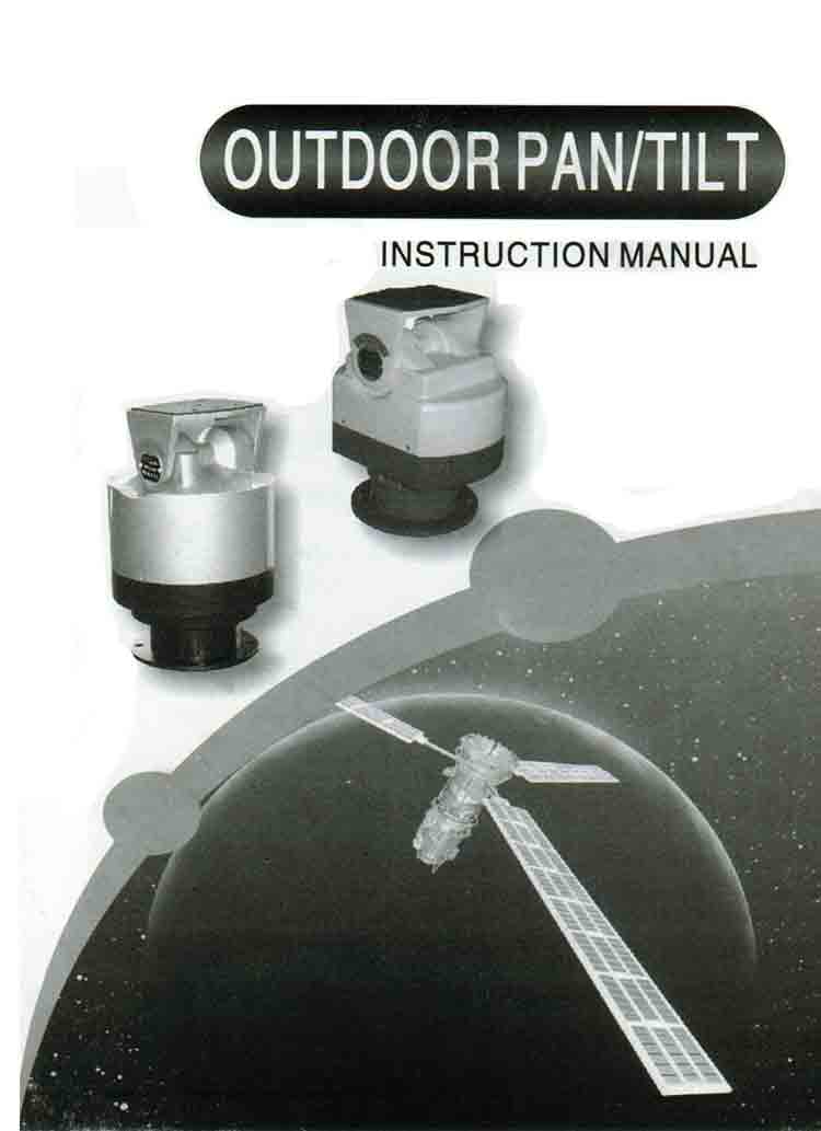 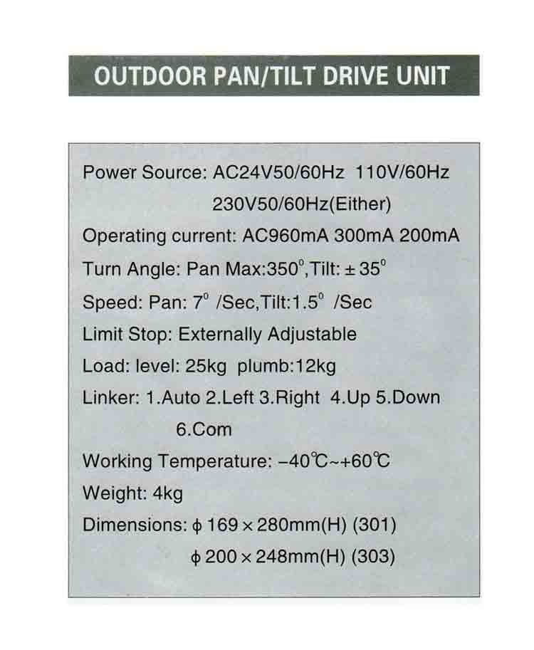 The connector on the current motor (pan tilt head) is a rectangular inline 6 conductor connector. 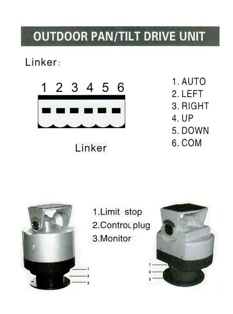 The connector on the current motor (pan tilt head) is a rectangular inline 6 conductor connector. 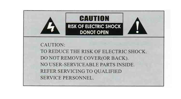 The connector on the current motor (pan tilt head) is a rectangular inline 6 conductor connector. |
|
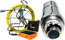
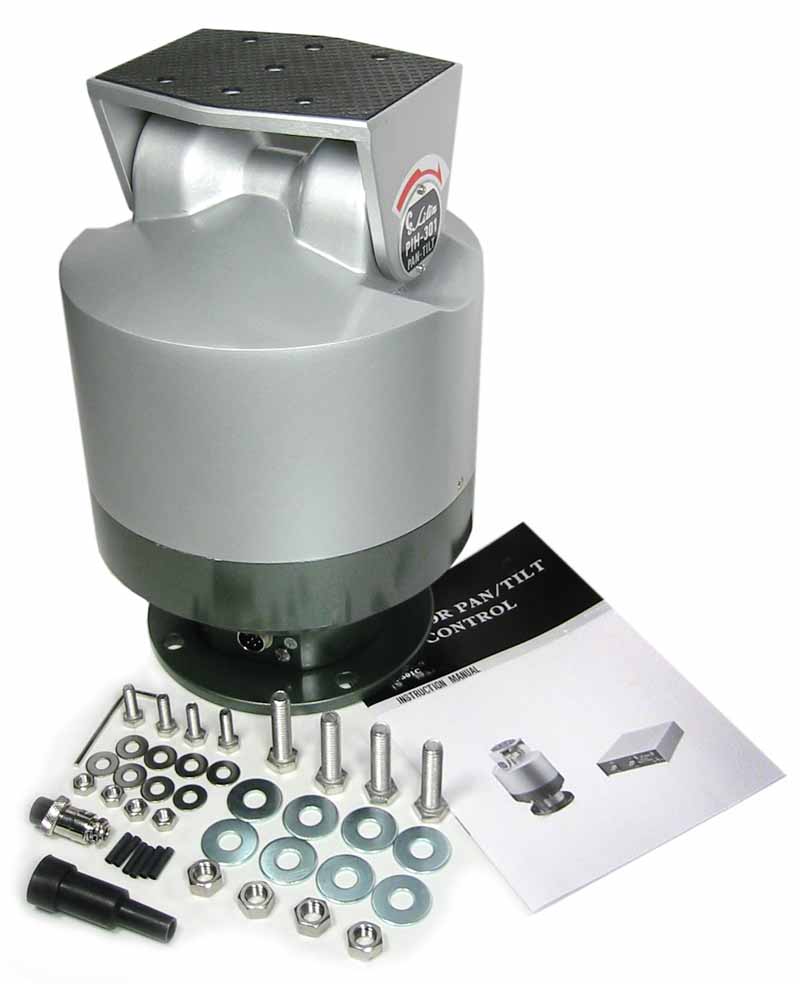 The current pan tilt head includes less hardware and a rectangular inline 6 conductor connector. |
|
 |
|
The connector on the current motor (pan tilt head) is a rectangular inline 6 conductor connector.
 |
|
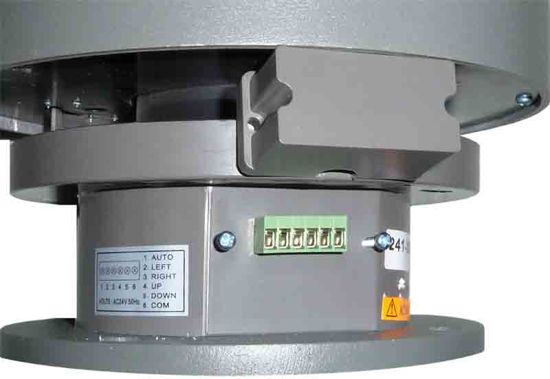 Note: the connector cover has been moved upward to show the connector. |
|
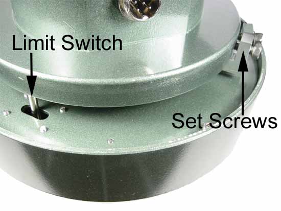
The connector on the current motor (pan tilt head) is a rectangular inline 6 conductor connector.
|
|
 |
|
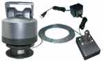
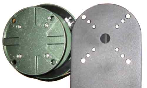 Pan tilt bottom and mounting bracket. |
|
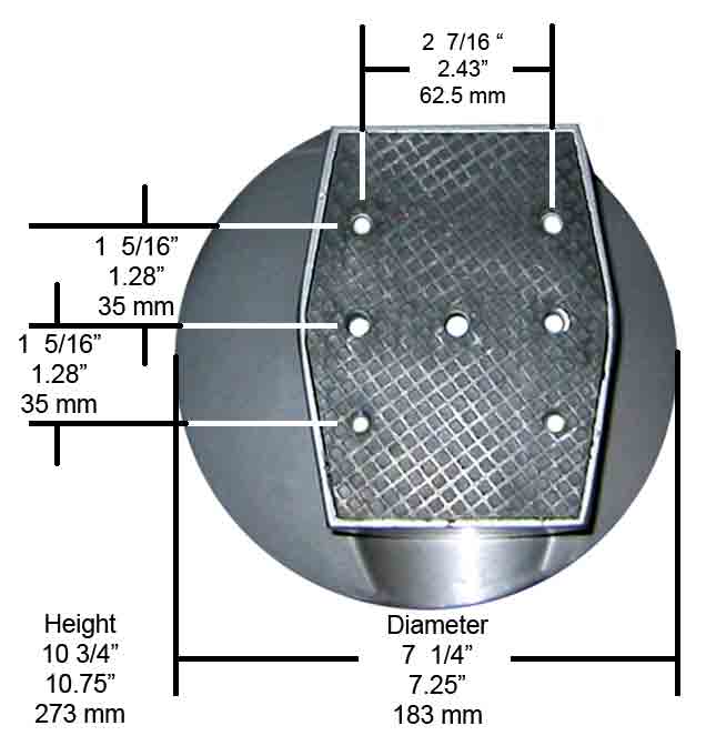
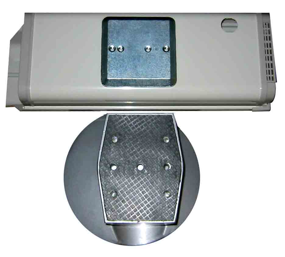 Bottom of the pan tilt weatherproof enclosure and the top plate of the PT1000 motor. |
|
 |
 |
Compare PT1000 and MP-101b. |
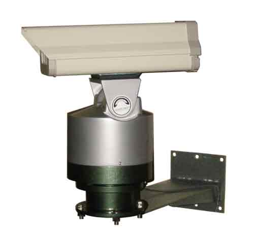
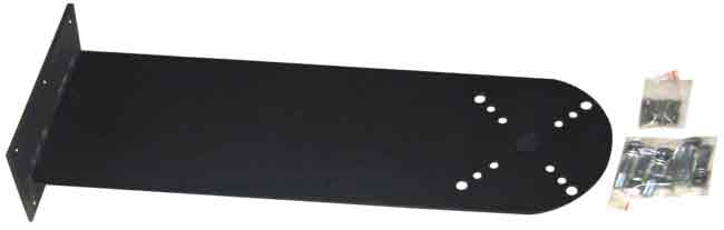
Pan tilt enclosure and mounting bracket. |
 |
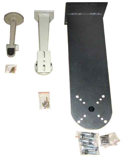 |
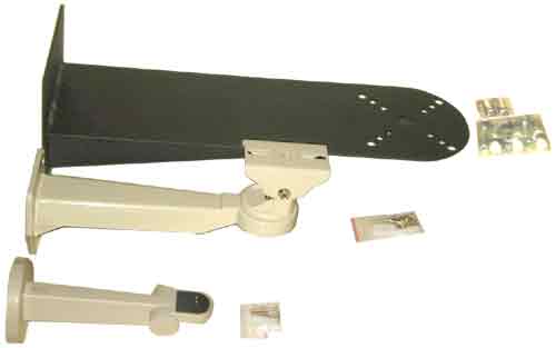
Compare three brackets. |
Compare three brackets. |
 |
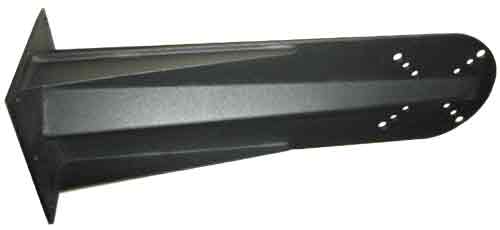 |
PT2000 mounting bracket. |
PT2000 mounting bracket. |
 |
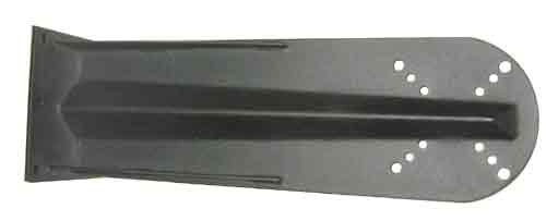 |
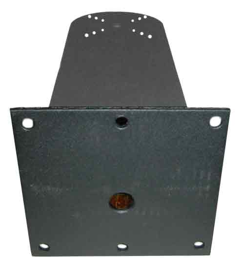
PT2000 mounting bracket rear. |
PT2000 mounting bracket bottom. |
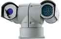
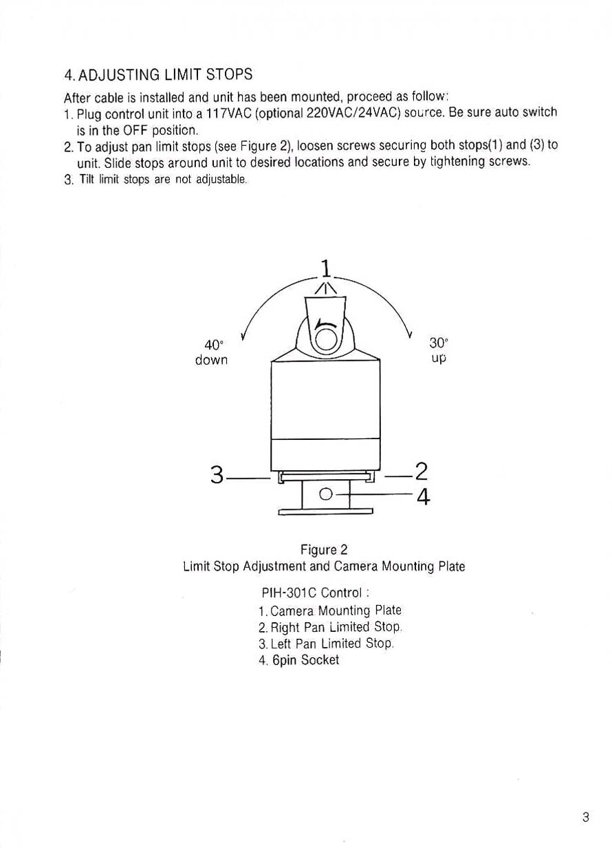
Outdoor Motorized Pan and Tilt.
|
|||||||||||||||||||||||||||||||||||||||||||||||||||||||||||||||||||||||||||||||||||
Allows you to move the camera up & down, right & left over a wired remote control. |
Manual for the Motorized Pan Tilt |
 Please see the newer manual at the top of this page. |
 |
 |
 |
 |
 |
|
Model # PT1000n Instruction manual (all text version) Weather proof, indoor or outdoor, motorized pan & tilt system. |
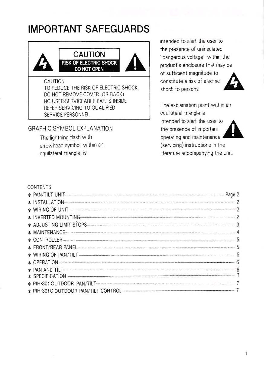
SAFETY PRECAUTIONS |
Disclaimer: Actual products may vary from photographs shown. We are not responsible for any unintentional omissions or typographical errors. We reserve the right to make changes to packages, services, operating procedures, colors, materials, features, specifications, part numbers and pricing. We may discontinue any product at any time without prior notice. |
 |
 |
 |
 |