|
|
|
||||||||||||||||||||||||||||||||
 |
|
||||
 |
 |
 |
 |
 |
 |
 |
 |
 |
|
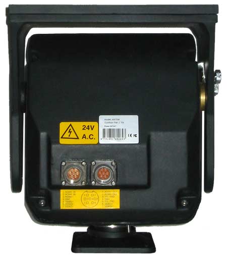
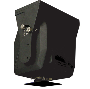
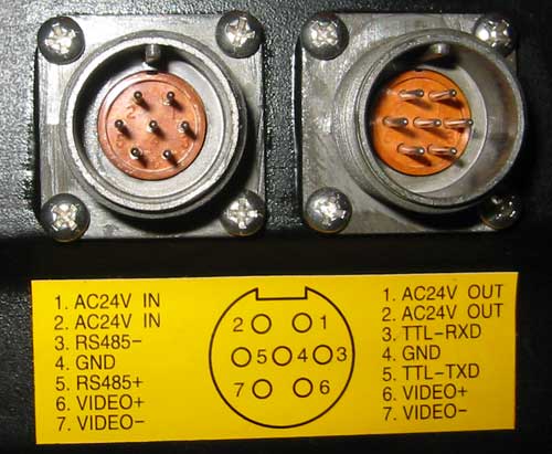
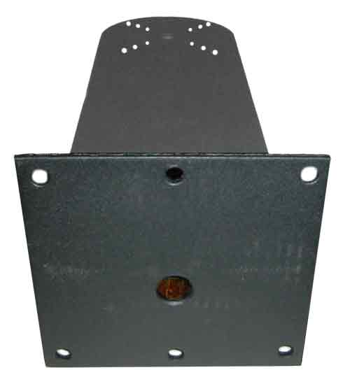
Front view. Controller connects to the left of the two connectors. |
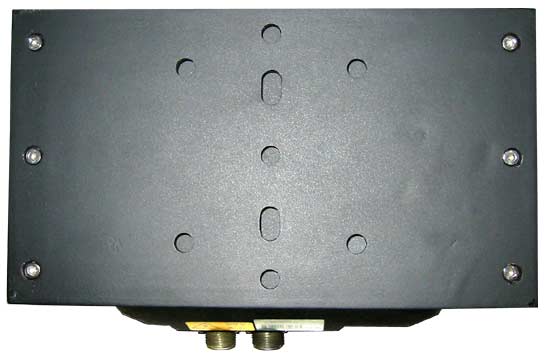 |
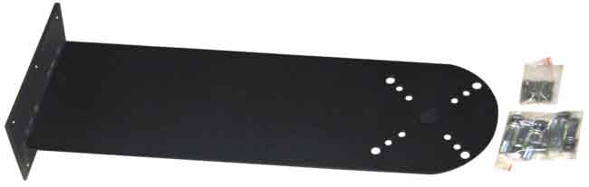
Top view. |
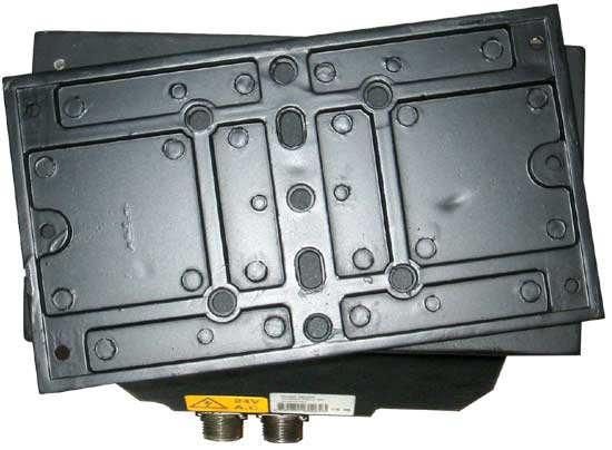 |
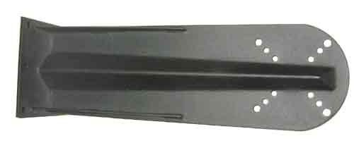
Top view. Camera mounting plate has been unscrewed and flipped over. |
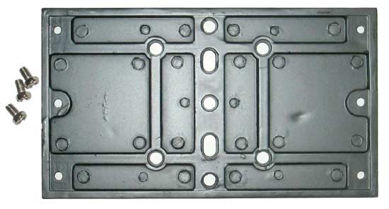 |
Camera mounting plate and the three 1/4-20 screws used to mount your camera to this plate. |
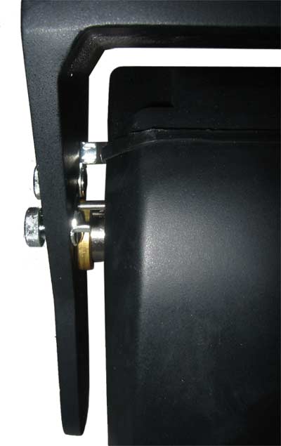 |
Side view showing the Tilt range adjustments. |
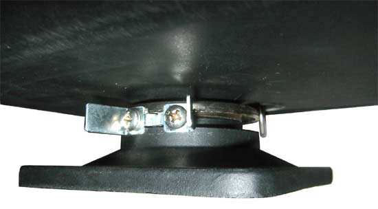 |
Side view showing the Pan range adjustments. |
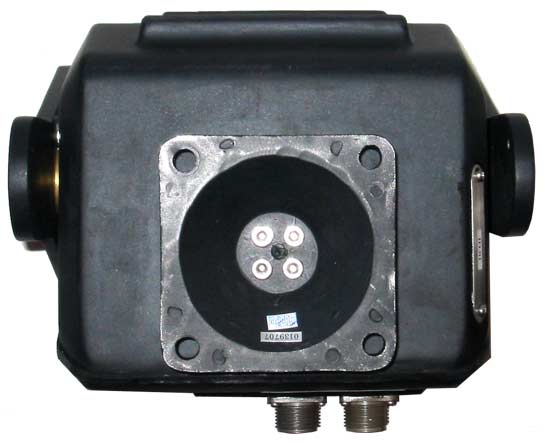 |
Bottom view and the 4 mounting holes. |
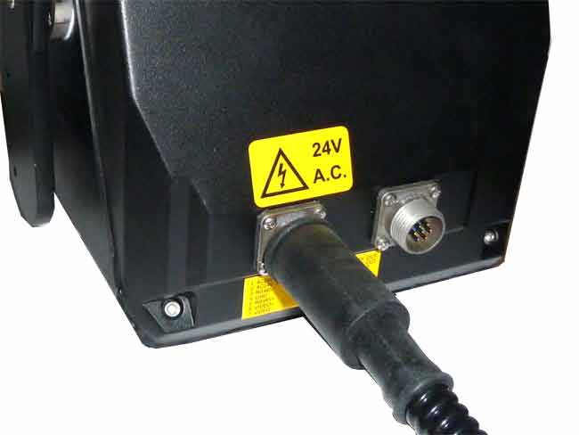 |
Side view Round connector with power and control |
Back view of the joystick controller showing the connectioons. |
Wiring the pan tilt system with power supply close to the joystick controller. Caution: reversing the power and control cables will instently destroy your motor! |
Wiring the pan tilt system with power supply close to the motor. Caution: reversing the power and control cables will instently destroy your motor! |
Wiring the system with 300 feet of control and power cable. Caution: reversing the power and control cables will instently destroy your motor! |
Daisy chain connection of multiple pan tilt motors. Daisy chain connection of multiple pan tilt motors with one joystick controller. .....Caution do not apply power (24 VAC) to the RS485 joystick control input, this will instantly destroy your motor.... 3.2 Selection of the Terminal Resistor: As shown in figure 1, DIP 10 of the ID-CODE is the select switch of the 120 terminal resistor on the bus RS485, on which only one terminal resistor of the dome camera at the farthest end can be connected, while the terminal resistors of other devices should be opened. |
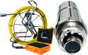
Replacement pan tilt outdoor cable. The motor cable is all black, 6 feet long, enclosed in a black corrugated flexible tube with a round metal connector that connects to the PT2000 motor on one end and two plastic terminal blocks on the other end. The red terminal block connects to 24 VAC power.The black terminal block connects to RS485 joystick controller. |
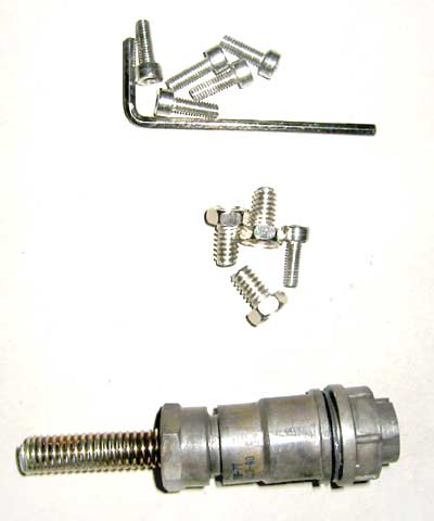 |
Hardware. |
 |
Cable Connector. |
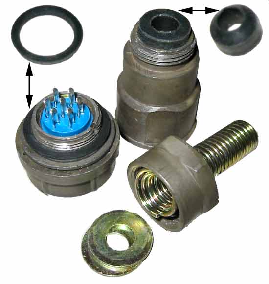 |
Cable Connector. Exploded view. Note the two gaskets (shown installed on connector and shown removed from connector). |
 |
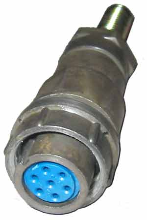
Pan Tilt motor Connectors. |
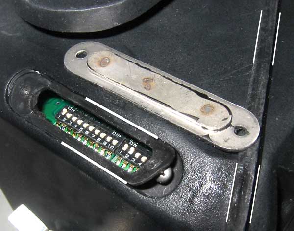 |
Dip switch cover plate. Note the cover plate gasket (between the white lines on the left side). Note the thick (0.2") gasket ring that travels all around the pan tilt motor (between the white lines on the right side). |
 |
 |
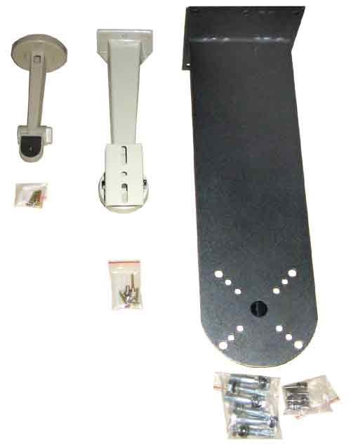
Compare three brackets. |
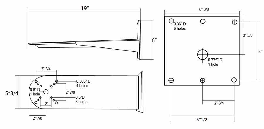
PT2000 bracket rear. |
 |
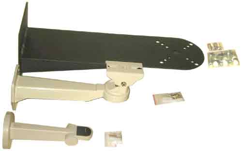 |
PT2000 bracket. |
Compare three brackets. |
 |
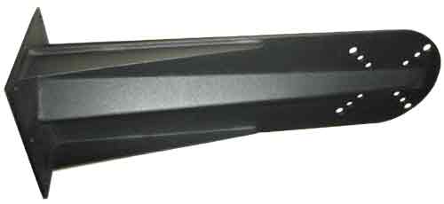 |
PT2000 bracket. |
PT2000 bracket. |
 |
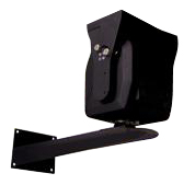 |
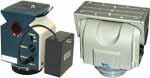
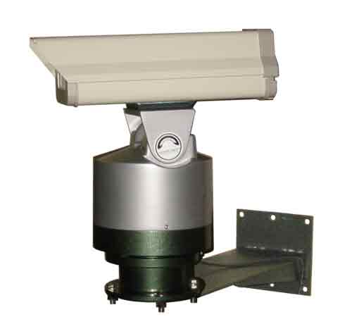
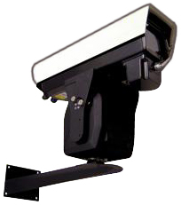
Pan tilt enclosure and mounting bracket. |
Pan tilt enclosure and mounting bracket. |
 |
|
Pan tilt enclosure and mounting bracket. |
SAFETY PRECAUTIONS |
CAUTION: Risk of Electric shock. Do not open. |
INDEX |
|
3.0 PAN TILT SETUP; 3.1 Address set SW1 is used to set address of the pan tilt from 1-511. The ID-CODE from DIP-9 to DIP-1 are equivalent to a 9 bit binary digit. DIP-9 is MSB while DIP-1 is LSB. The state "ON" of each bit means 1, while "OFF" means 0. Page 2 |
3.2 Selection of the Terminal Resistor: As shown in figure 1, DIP 10 of the ID-CODE is the select switch of the 120 terminal resistor on the bus RS485, on which only one terminal resistor of the dome camera at the farthest end can be connected, while the terminal resistors of other devices should be opened. 3.3 Setup of the Protocol and the Default Baud Rate: As shown in Figure 1, SW2 is used to set the protocol of communication and the baud rate used by the dome camera. DIP-4 to DIP-1 of SW2 is used to select protocols and 16 different protocols can be selected in maximum. Following table shows states of coding switches of protocols selected by the dome camera in which means the protocol has be integrated while means the protocol is temporarily vacant. Page 3 |
Some protocols and the states of the coding
switches of normal baud rate of the protocols are shown as follows: 3.4 Setup of the Baud Rate of Communication: As shown in Figure 1, SW2 is used to set the protocol of communication and the baud rate used by the dome camera. DIP-6 and DIP-5 of SW2 are aside to select the baud rate of communication and 4 different baud rates can be selected in maximum. If the controller adopts nonstandard baud rate, you can adjust it to be identical with that of the controller as per the following table. 4.0 CONNECTION DETAILS: Notice: Before carrying out any electrical installation ensure that the cable being used is at the correct voltage and current rating for the application. Page 4 |
4.1 Connecting Pan Tilt with the Controller: RS485 control signal, power supply (AC 24V) and video signal connect with the controller with a weather proof connector plug (D1). Figure 4's connection diagram is D1. Figure 3 is the cable that is soldered to the weather proof connector. 4.2 Connection of Pan Tilt and outdoor housing: When collocate the special decoder for housing, decoder's control signal input. Power supply (AC 24V) and video signal output by weather proof connector plug (D2) to connect. Figure 5 is connected way of D2. Note: Connect Pan Tilt's Ground with lens decoder's Ground Furthermore P/T's TXD, RXD must cross connect with lens decoder's TXD, RXD. Otherwise, lens will not to be controlled. Otherwise, could not to preset lens's position, only just could preset pan tilt position. Page 5 |
|
7. SPECIFICATIONS Input Voltage: AC 24V Angular Travel: Pan 350. Tilt +20 -90. Speed: Pan 0.25-10/second. Tilt 0.25-10/second. Limit Stop: Externally adjustable Load Rating 15 KG's (Over The Top MOUNT) Operating Temperature: -35c-+60c Construction: Aluminum alloy casting Measurement: 225(L) x 180 (W)x260(H) (Over The Top MOUNT) Unit Weight: 10 Kg Page 7 |
Pan Tilt Zoom (PTZ) CCTV cameras
are affordable and offer better performance then ever.
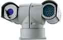
Pan Tilt Zoom surveillance cameras are used by Government, large corporations, casinos and consumers. Other uses include Mast Aerial Photography. PTZ cameras rotate horizontally through 360 degrees, vertically through 90 degrees and have motorized optical zoom lenses. A camera turret or motorized swivel is similar to a pan-tilt head. Pan Tilt movement can be very fast and is controlled through a wired (or wireless) connection, by the mating controller. PTZ cameras are often mounted in domes, outside dome cameras are weatherproofed, heated and cooled. |
 |
 |
 |
 |